
 Project COBRA'33
Sponsered by:
WIRING
The Engine
Project COBRA'33 has 3 different wiring systems for the engine and transmission, each different and extremely important to the overall function and performance of the car.
1. OBDII and Factory Electronic Fuel Injection
2. Innovate Motor-sports digital monitoring
3. Dakota Digital gauges
1. OBDII and Factory Electronic Fuel Injection
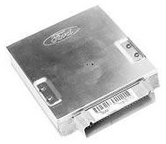
This system is the wiring necessary to run the factory computer. This includes all the different sensors and actuators needed in order to run and manage the fuel injection system. It includes information received by its many Temperature, Pressure, Position and Oxygen sensors it uses to manage the ignition, fuel and transmission systems.
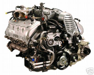
The Ford 4.6L DOHC 2003-2004 Cobra Engine also known as the "Terminator"....This is exactly how it looked when we purchased our new engine.
The Engine:
Project COBRA'33 uses a Ford 4.6L DOHC supercharged engine that we modified for our use. The factory wiring harness was discarded as it was no longer up to the task of supplying our engine with the information now needed. In its place, we went with a custom made engine wiring harness which supplied the engine with the many different signals and voltages needed without the EGR system and its associated plumbing & wiring.

The Detail Zone www.thedetailzone.com
The Detail Zone, a very accomplished and professional engine management business, supplied us with the correct wiring package. We used their Telorvek system which consisted of all the correct engine and transmission connectors attached to 10 feet of wire. This gives the user the ability to make the necessary connection and then run the wires back to which ever spot they want, and then terminate those wires to the Telorvek panel. The Telorvek panel, is a huge benefit for the hot rodder, it allows you to place the factory computer anywhere in the car you want, not just under the dash. In a car like our Project COBRA'33, there just isn't much room under the dash, especially once you mount the gauges and the AC unit. The Telorvek panel will allow us to mount the computer in the rear of the car, away from the dash and all its confinement. The Telorvek system is really an auxiliary panel that also has all the connectors needed to plug right into the factory computer. This allows for a neat and very custom wiring job, that also gives instant and easy access to all the system's many sensors and actuators. The panel, which closely mimicks the functionality of a break-out box, literally connects to every needed engine and transmission function. This puts every sensor, switch and actuator the engine/transmission has, right at your finger-tips awaiting future trouble-shooting or probing. Imagine, being able to access every vital electrical part in one convenient, well-lit place!
The Telorvek EFI System....makes EFI possible for almost anyone. This is essentially what our kit looked like, we had the Telorvek panel and an assortment of pre-terminated connectors.
The Detail Zone supplied us with the needed connectors, each pre-attached to its own 10 foot length of wire. Simply make the correct connection to the engine or transmission and then just route the wires back to the Telorvek panel and connect them to the proper terminals, it doesn't get much easier or nicer than this. The Telorvek panel takes all these connections you made coming from the engine/transmission and combines them into one large group of wires that simply plugs into the factory computer. No wonder the Detail Zone and their Telorvek system are growing so quickly, they make a huge undertaking into a manageable exercise.
What it takes to make it happen:
Engine:
Mass Air Flow Sensor: 4 wires Attaches to the M.A.F. sensor which is located between the air filter and the intake throttle body.
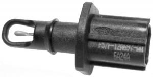
Intake Air Temperature Sensor: 3 wires Attaches to the IAT sensor which is located just behind the MAF sensor, and plugs into the intake plenum.
Engine Coolant Temperature Sensor: 2 wires Plugs into the ECT sensor located in the front of the engine down behind the supercharger snout.
Throttle Position Sensor: 3 wire Plugs into the TPS sensor located on the passenger side of the throttle body.
Idle Speed Control: 2 wires Plugs into the ISC located on the top of the throttle body intake manifold.
Barometric Air Pressure and Air Temperature Sensor: 4 wires Plugs into the sensor located to the drivers side and back of the superchargers manifold.
Supercharger Bypass Solenoid: 2 wires Plugs into the the solenoid located on the drivers side of the supercharger.
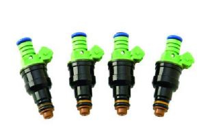
Injectors: 5 wires each side, total 10 wires There are two (2) banks of fuel injectors, one on each side of the engine. They are located in the intake manifold and are held in position by a fuel rail which is bolted in place to keep the injectors securely mounted. The top of the injector goes into the fuel rail, where it gets its supply of fuel and the bottom of the injector goes into the intake manifold, where it sprays its fuel. Everything is kept leak proof by O-rings, which are mounted on each end.
Ignition coil: 5 wires each side, total 10 wires This like the injectors has wires that go to each side of the engine. The coils are located under the coil covers in the center of each valve cover. Remove two (2) screws in the coil cover to access the coils. Directly located above each spark plug is the coil that goes to that cylinder, this is the Ford coil on plug system. Plug in the corresponding plug to its matching coil and route wires out of the coil area through an access hole in the coil cover. Take the time needed to avoid any wires getting pinched under the coil cover.
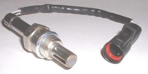
Oxygen Sensors: 4 wires each, 8 total wires The factory included four (4)-Oxygen sensors, two (2) were front mounted, in front of the catalytic converter, and these were used by the engine software to make changes in the close loop mode, to the fuel mixture. The rearward two (2) are used in the factory system for emissions, and will be deleted in our project car.
Crank Position Sensor: 3 wires This plugs into the CKS sensor located in the front bottom part of the engine. This sensor is used to tell the computer where the crankshaft is in relation to degrees at top dead center.
Camshaft Position Sensor: 3 wires This CSP sensor further refines the information regarding engine timing. It tells the computer where the camshaft is regarding timing for the number one cylinder at top dead center. The sensor is located on the drivers side front of the engine.
Data Link Connector: 16 wires DLC Is used to send and receive data from the factory computer. It's mounted under the dash and on the driver side.
Wire count: 70 individual wires
Transmission: Late model 4R70W (AODE), electronically controlled four speed automatic transmissions.
Main Transmission Plug: 8 wires Located on the passenger side of the transmission. Controls most electronic transmission functions, from torque converter lock-up to gear selection.
Digital Transmission Range Selector: 10 wires Mounts on the drivers side of transmission directly over the range selector stud. Takes care of neutral safety switch, back-up lights, and gear selection.
Transmission Speed Sensor: 2 wire Located on drivers side mid-length back. Works with other sensors to control proper shift points and torque converter lock-up.
Wire Count: 20 individual wires
Total wire count: 90
This represents the basic system and in no way represents the complete package, there are many more systems that need to be wired. The Ford EEC V computer has 104 electrical connections, and we have only used 90 at this time. Other systems that will need to be wired in are the electric fans, fuel pump, transmission control switch and several others. Also, the above electrical connections are for our project only, there are several different versions of the 4.6L engine, and each version has its own set of needed connections.
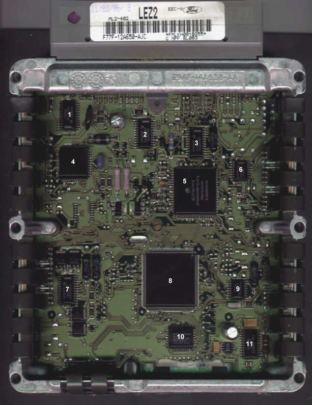
A look inside the Ford EEC-V computer.
| 1: 71016SB 24 pin SOIC MAA45U01 XAB9642 Motorola |
2: 710014FSE 24 pin SOIC MDB67M02 XAB9640 Motorola |
| 3: MBA68M02 24 pin SOIC 710015FSE XAH9638 Motorola |
4: DIS 6 ML2 44 pin PLCC 6 G F 5020SC030 QQPL9631 5E72T
IDENTIFIED!! DIS Ignition Controller |
| 5: SC370674FN 68 pin PLCC N700009BFSCHFA MBA500U01 NJQQB9640 Motorola |
6: 71002AE 16 pin SOIC MAA93U01 XAC9640 Motorola |
| 7: 71012SE001 24 pin SOIC MCA61U01 XAE9637 Motorola |
8: EPIC AM01BC 160 pin QFP N7500230FSCGMD 185 MBB409U01 YQCU9641 Motorola
IDENTIFIED!! EPIC Co-Processor |
| 9: 71004SL 16 pin SOIC MAA17T03 XXAA9642 Motorola |
10: N70005FWCHCA 32 pin PLCC IBA491U01 U6390282 7B0 FoMoCo Intel C '91 '95 IDENTIFIED!! Intel 28F010 FLASH PROM |
| 11: 70068FB 24 pin SOIC 885S03 CS9642S Motorola |
2. Innovate Motorsports digital monitoring

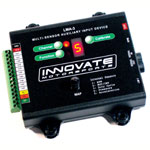
We are using Innovate Motorsports equipment to capture engine and transmission running data. We then in turn use this information to more finely tune the ignition and fuel system. The system monitors oil, fuel and boost pressure....transmission fluid, inter-cooler water and cylinder head temperature....Exhaust gas temperature and Oxygen content on each side of the engine's headers .....as well as several other important and useful engine functions. The system is discussed in more detail elsewhere on this site, but knowing what is going on inside the engine at any given time helps us tune for more power and hopefully will also aid us in avoiding trouble.
Summary of what is needed
Pressure Sensors
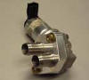
Fuel Pressure sensor: 3 wires Mounts to the fuel pressure by-pass regulator. Is used so we can observe any major fluctuations in fuel pressure, which could lead to tuning issues as well as engine damage.
Oil Pressure Sensor: 3 wires Mounts on the bottom front drivers side of the engine. Monitoring oil pressure is simply a good idea, since all engine operations depend on a constant pressurized flow of clean engine oil.
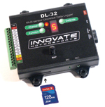
Boost/Vacuum Pressure: Built into the DL-32 and Aux Box. We simply run a vacuum line form the engine to the component. Both Boost and Vacuum are important engine tuning conditions, we will monitor these two conditions as part of the overall picture.
Nitrous Oxide Bottle Pressure: 3 wires Since ProjectCOBRA'33 will be using Nitrous Oxide to boost it's performance, we want to make sure we monitor the bottle pressure, which efects the tune. This requires a special high pressure sensor, one that registers 0-2500psi.
Temperature
Inter-cooler Water Temperature: 3 wires By monitoring the inter-cooler water temperature we can get the intake air temperature after the inter-cooler. This is useful because it will allow us to alter the intake air temperature if the monitored temperatures are too high, which can cause a loss of power and more importantly, detonation.
Automatic Transmission Fluid Temperatures: 3 wires Transmission fluid temperatures need to be monitored to avoid damage to the transmission. You want the temperatures to come up to normal operating range as soon as possible. This allows the transmission fluid to warm-up and flow as designed, resulting in smooth efficient operation.
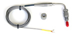
Exhaust Gas Temperature: 3 wires each 24 wires total Temperature readings will be taken from all 8 cylinders of the engine. The EGT probes will be mounted in the Tops of the header system, and readings will be recorded for tuning purposes.
Fuel Temperature: 3 wires Fuel temperature will be monitored to make sure the return-type fuel system is not generating excessive heat, which would hamper performance and could lead to detonation.
Cylinder Head Temperature: 2 wires each 4 wires total Each cylinder head is monitored for temperature at the back rear most portion of each head, using the same space the radio capacitors were located. Knowing the cylinder head temps gives us another look into what is happening inside the engine.
Engine Oil Temperature: 2 wires each 2 wires total. By monitoring engine oil temps we can better understand what is happening on the inside.
Other Sensors
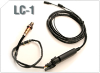
Wide Band Oxygen Sensors: 4 wires each 8 wires total Monitoring the Oxygen content of each side of the engine gives us a very good representation of what is going on inside our engine, and where we are at in relation to our tune-up.
RPM: 1 wire but 3 wires for the tach adapterWe will have to use the AutoMeter Tach Adapter to gain the tach wire the system needs.
Speed: 1 wire We will use the transmission speed sensors output wire to the EEC for our speed sensor input. Just tap into the signal at the Telorvek panel and program the device for the correct ppm.
Ignition Advance: 1 wire Use the cam position sensor or crankshaft position sensor and tap into the signal at the Telorvek panel.
Throttle Position Switch: 2 wires We will track the position of the throttle valve and use it to confirm throttle position.
Total Wire Count= 64 + hook-up and interconnecting wiring
3. Dakota Digital gauges
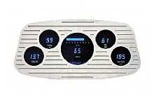
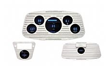
Project COBRA'33 uses digital gauges manufactured by Dakota Digital. These gauges monitor oil, fuel and boost pressure as well as engine coolant, transmission oil and inter-cooler water temperatures. In addition, Dakota Digital gauges supply us with RPM and speedometer functions as well as turning signal, high beam, shift, and gear position warning indicators. The gauges use specific to Dakota Digital sensors which we will wire into the system.
Engine Coolant Temperature: 1 wire Sensor is located with factory engine coolant sensor in the front top portion of engine.
Engine Oil Pressure: 1 wire Sensor is located with factory oil pressure sensor at the bottom drivers side front of engine.
Fuel Level: 2 wires Sender is located in the rear of the vehicle, inside the fuel tank.
Speedometer: 2 wires Sensor is attached to the drivers side of the automatic transmission, and connected to the speed sensor.
RPM: 1 wire Picks up signal from Innovate box.
Turning Signal Indicator: 2 wires Simply ties into the existing turning signal circuit.
High Beam Indicator: 1 Wire Ties into the existing high beam circuit.
Malfunction Indicator Light: 1 wire Wire run back to the EEC and ties into the Telorvek panel.
Transmission Gear Indicator: 2 wires A stand alone gear selector is mounted to the drivers side of the transmission.
Overdrive On/Off Indicator: 1 wire
RPM Warning Light: 1 wire
Total Wires 15 + hook-up and interconnecting cables
TOTAL WIRE COUNT
Telorvek Panel: 90
Inovate System: 64
Dakota Digital: 15
TOTAL 169
Building the Harness:
If you have been following along, you can see that we've made/routed/terminated at least 169 electrical wires for the above three (3) systems! That's a lot of wiring, and what's more important is it's a lot of chances for a mistake. Nothing you do on a project like this, will help you more, then practicing good solid basic craftsmanship-like skills. That means keeping your eye on the overall picture, but making sure that no matter what the task is at hand, you work on that task and give it your all, 100% and nothing less. It's very easy to lose sight on the smaller projects and overlook things, this is how projects sink. I don't know of anything more aggravating and demoralizing than trying to track down a bunch of wiring problems. And the worst of them all is the loose connection or on-again off-again short.
While the Detail Zone does a great job of supplying the necessary pre-terminated connectors and Telorvek panel, the actual wiring and lay-out is up to you, the installer. As with any type of specific undertaking, there is always a list of needed tools and supplies one must have to do the job right. Automotive wiring is a very important part of any Hot Rod project. Since most everything runs on electric, it would be very easy to say Automotive Wiring is the MOST IMPORTANT part of any Hot Rod, Street Rod or Truck project. In fact I can not think of any other part of building a Hot Rod that is as important as the wiring. For this reason, you should treat it as such. Make it your priority when working on it.....that means only do wiring when you are wiring. So often we jump around from one task to the other, I'm as guilty of it as anyone. I don't know how many times I've been working on a piece and saw something that was forgotten or needed to be done, and jumped right in and dropped everything to fix it. This is OK on some items, but not when working on the electrical system, this is how problems get started. So now we know what to do, right? STAY FOCUSED!
There are many decisions to make when doing the wiring portion of any project, and good decisions will make your project run smoother. We were contemplating where and how we would run the electric way back at the start of this project, when we were working on the frame. I installed conduits in each frame section that ran the length of the frame, this way we could get all the signal lighting ran without notice, and the other side was for the main power leads from the battery to the starter and engine block for the ground. It's this forward thinking that saves time and makes jobs like this go smoother.
Buying the correct electrical parts and more importantly TOOLS, for your project is very important. Hot Rodders tend to use many different makes and or models as their source for parts, so it is extremely important that you purchase the right part and or tool for its application. Take our Project COBRA'33 for example, we are using a 2004 Ford 4.6L DOHC Cobra engine and mating it to a Ford 2001 4R70W (AODE) transmission. This is a combination that was never realized at Ford, they never offered their Cobras with the option of an automatic transmission, never! This of course doesn't mean that it can not be done, but by choosing this combination you are going to have to work harder than if you chose to mate our engine with a 5-speed manual transmission that was offered with the Cobra package. The same holds true when adding sub-systems to your project like the Innovate Data acquisition system. These systems add to the complexity of an already complex system, so extra care MUST be taken to assure everything works together. The sheer number of electrical wires alone is cause for concern, both because of the potential for wiring errors and the problems physically trying to conceal and protect so many circuits.
TOOLS
Complete line of Electrical Tools available at:


Klein tools offers quality professional grade tools specifically for the tradesman.....as does Channel Lock and Sears Craftsman tools.
Electrical work requires the use of special tools, so if you plan on doing your own electric on your project pick yourself out a good collection of quality tools.
Stripper
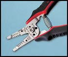
This is a quality set of strippers, they have plier ends, strip both solid and stranded wire, incorporate a wire cutter and even small screw cutter into the design. Best yet, the blades are stainless steel!
Main function is to remove the outer insulation from around the wire. Most strippers come with some sort of other function, such as crimper, small bolt cutter, or wire bender. These extra functions are nice, but don't lose sight that the main function should be to strip the wire of its insulation. Buy a great stripper first, and what ever extra function it comes with be considered a bonus. I like my strippers to be comfortable, and have large padded hand grips. For multi-function strippers, I like the ones with a pliers function in the front and wire cutter option in the rear. Good wire strippers will run $20-28, depending on the style and extra functions.
Crimpers
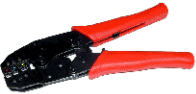
A great Ratchet Type Crimper, this one has replaceable dies.
Crimping tools are another indispensable tool when doing automotive electrical jobs. Most kits sold come with Insulated Crimp-on Type Connectors. This is where so many go wrong, they use the wrong crimping tool for the job. Insulated connectors are to be used with special crimping tools that do not compromise the terminals insulation. There are several brands and even several styles, but the best ones for insulated terminals is the one pictured above. It crimps the terminal with much force, using a ratchet type mechanism and will not let go till the proper force is applied. This makes sure all your terminals were crimped right. This type of crimper will also not damage the insulation on the terminal, making it the perfect crimper for insulated type terminals. Some even come with replaceable dies, which is a great feature in case you should happen to damage one. Also, most crimpers that have replaceable dies, will also offer other die sets, for crimping Non-insulated terminals, and for crimping special terminals like the weather PAC connectors we will be using later. The cost for a good quality set of hand crimpers is between 30 and 40 dollars, money well spent if you plan on doing your own wiring.
Wire and Cable Cutters
This is another must have set of tools. I like to use a quality set of Diagonal cutting pliers for the smaller wires, gauge #10 and smaller. For the larger wires I use a set of Cable Cutters, ones that can cut up to #1 gauge wire pretty easily. You should consider these two tools as a must, and order yourself a quality pair of each. Channel Lock makes very nice Pliers, I have their entire line of pliers and think the world of them. Another quality plier maker would be Klein Tools, they have been making electrical tools for over 150 years, they know what you need and do a good job making them.
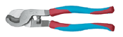
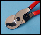
Channel Lock with their new "Code Blue" and Klein's small cable cutter
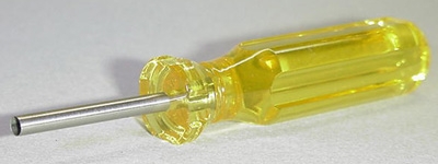
Screwdrivers
These are something most people would already have, but I still want to mention them. You are going to be using different size screwdrivers both flat blade and Philips a lot, every wire to the Telorvek panel lands with a screwdriver. Same holds true for most fuse panels, sending units, and a host of other devices. You are going to need an assortment of screwdrivers in various lengths and styles to complete your project. Get yourself some quality tools and be done with it. Sear Craftsman tools are great, I just don't care for their line of pliers. The best screwdrivers are probably Klein tools, they have hardened tips, and big cushion type grips. I love to use them. Klein used to be hard to find, only true electrical supply houses sold them, but now they are much more common. Home Depot and even Sear stocks them.
![]()
![]()
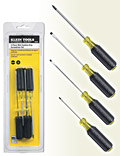
Quality Klein Screwdrivers, the multipacks offer great savings
Pliers
You will need an assortment of pliers, and both Klein and Channel lock offer a great line-up from which to choose from. .
Diagonal Cutting Pliers
Crimping Pliers
Slip joint
Tongue and Groove
and many other specific styles of pliers: Channel Lock offers several styles as does Klein, but Channel Lock gets the nod here, they are by far the best pliers manufacturer with few noted exceptions.
Other tools to consider are:
Test light
Digital Volt Ohm Meter
Soldering Gun
Heat Gun
Small Bench Vise
And Any Special Tools Needed
Like for the Weather PAC Connectors
Supplies
Carries all your electrical and wiring supplies
Along with tools, your going to need some specific electrical supplies.
Ty-Wraps: These are not very expensive and I would buy an assortment of them ranging from 4" to 14". They come in all colors and if you want to create a theme, well that's up to you, but Ty-wraps come in handy when you need to support some wires or hold a group together.
Electrical Tape: Here there is only one choice, 3M Scotch 33 tape.
Harness Warp: When grouping a bunch of wires together to form a harness, you do not want to use electrical tape, you use Harness Wrap. This is very thin vinyl wrap that does not have adhesive on the one side like tape, this is preferred because it does not leave the wires all sticky when removed, and it goes on much better than tape.
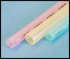
Shrink Tubing: A protective covering that is used to insulate and protect the wires. It comes in several different styles and thicknesses depending on what type connection needs to be covered.
Single Wall-Shrink Tube: Comes in several different sizes to meet all your wire gauge needs, and comes in both red and black colors. I like using this to cover a group of wires to form a harness. It does not contain any adhesive, so it can be removed very easy without damaging any wires in the harness. It also works well on covering other shrink tube products for a finished well protected connection. Most Shrink Tube products are available on rolls, but several only come in 4 foot or smaller sticks.
Translucent and Clear Shrink Tube: I like using this to seal connections and joints from the elements and anything else that could work it's way into the joint and cause problems. Many times the locations in which wires and cables are used contain corrosive or other damaging conditions like moisture, Dirt, Grease, gasoline and engine oils. These substances along with high temperatures, extreme conditions, and vibrations, make it difficult to seal connections and joints. Since any one or a combination of the above can cause loss of signal strength, voltage drop and or shorts, it's imperative that we take the time and materials to address these concerns before they become a problem. Shrink tube is a covering, that comes in several different styles and thicknesses and is used to cover and protect electrical connections and joints. It can also be used to group and protect individual wires, as well as hoses.
Translucent Shrink Tube: is great for most terminals and but splices, just slide the appropriate size over the wire prior to making the connection, then pull the shrink tube over the connection and heat with your heat gun till it fully shrinks and envelops the connection. I then use a piece of single wall to further cover and seal the connection.
Clear Shrink Tube: For protecting joints and connections from the worst of all conditions, use the clear shrink tube in place of the translucent. This type of shrink tube has an adhesive built into it's inner layer that when heated, melts and completely in-cases the joint or connection in a A thick wall of modified polyimide adhesive which melts and flows, encapsulating and sealing components contained within. Just make sure the connection you are about to seal is correct and finished, cause this stuff isn't coming off. I usually use a piece of single wall tubing as an outer covering after the clear shrink tube has had time to cool.
Triple Wall- Shrink Tube: Triple-wall adhesive polyolefin tubing will deliver the ultimate protection for battery cables. When heat is applied it will bond permanently to your cable and give it not only a professional look but also a professional performance. These come in both Black and Red colors, and are used only on the vehicles main power connections, like the battery, alternator, cut-off Switch, Power Amp and Starter circuits as well as all major ground connections.
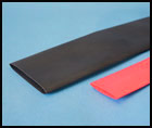
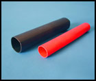
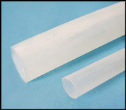
Translucent Single-Wall Triple-Wall Clear Shrink Tube
Electrical Terminals: You will need an assortment of terminals, so if you do not have any it may be a good idea to buy yourself an assortment of all the different terminals from a quality electrical supply house. Avoid the urge to buy the cheap terminals from some of the vendors that sell mostly Chinese tools, they are just not up to the task. Vendors like and ProWeld Performance Parts sell quality electrical terminals.
GM Packard (GM-P) Weather-PAC Connectors: Your project may or may not use these, I used them on Project COBRA'33 for several items. The engine harness used two (2) large weather-PAC connectors to separate it where it goes from the engine into the firewall. This way the engine wiring could be completed, without the burden of all the wires being draped all over the engine. Now we simply have two connectors hanging there. Same holds true for all the other systems, you can go ahead and make all the connections and build the harnesses, then just terminate the wires in the spot you want with a weatherproof connector. There are several designs available from a single conductor to 6, and a 22 conductor bulkhead fitting like we used. I plan on using them exclussively on Project COBRA'33 for many of the electrical connections like tail lights, headlights, and so fourth.
Weather-PAC connectors consist of a male and Fe-male housing, 2-pins (male and Fe-male) and two seals for every conductor .
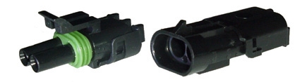
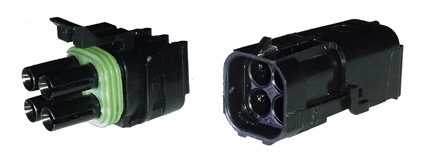
Weather-PAC connectors....a two and four conductor housing.
PLANNING
That's right just like anything else, electrical systems take very careful planning. Look at each system by itself, figure out what it needs and where you are going to have to go. I like to write things out sort of like what we did above, this way I can see it and better visualize it. Once you have all the electrical systems listed and what each one requires, then you can start to get the overall scope of the project and what it's going to take to make everything work together. Nowadays the audio and video systems are more complex than ever, don't forget to include these systems when you list everything. Modern sound systems use enormous speaker and amplifier wires, and you have to know the number and size so you can properly supply and route these wires. We will list the requirements for ProjectCOBRA'33's audio/visual system later, as well as all the other sub-systems.
When you first start to assign color and gauge values to the wires needed on your project, you can first eliminate the circuits that have already been taken care of. As an example, all the wires from "The Detail Zone" that go with the Telorvek panel have the proper terminal number and abbreviated name printed on them all along the length of the wire. This is super nice, because it means you can not grab the wrong wire, the terminal number where it connects to the Telorvek panel is printed on the wire, how much nicer could it get? This eliminates some 90 chances for a wiring problem, if only they were all like that.

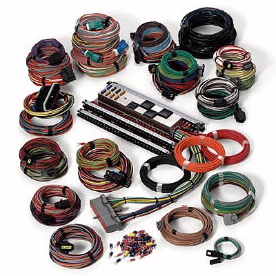
You can make things even nicer for yourself and purchase a quality wiring kit. These kits come in all sizes, to fit just about any job, and like the Telorvek Panel they have the circuit name printed on the outer jacket of insulation of the wire. We purchased a Ron Francis wiring kit for Project COBRA'33.
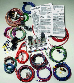
This is the XP-67 Ford Powered wiring kit be used for Project COBRA'33
It's there EXPRESS KIT, part #XP-67 - Ford Powered Express Wiring Complete Wiring System, the kit comes with most every circuit we will need. Of course there are always options so that you can tailor the kits to your exact wiring needs and we will need to purchase a few. But by purchasing the kit you get 90% of everything you will need, including the fuse block and step-by-step instructions. We opted to also purchase their complete grounding system with bus bar, and I would recommend that everyone else does the same. Grounding is a very important part of any modern Electronic Fuel Injection System. The computers depend on them for signal shielding. Sensors use the ground wires for return paths and actuators use them for proper function. Many reports and books I have recently read suggest that improper grounding is the number one cause for common EFI installation problems. Don't overlook the grounding system on your project, with the simple addition of a quality grounding kit, and a dedication to ensure that you take the time to properly ground all your grounding connections, you are well on the way to a trouble free installation.
PURCHASING
This is the stage that everyone can relate to, the actual spending. Now that you know what you want, and where it goes, you can shop around for the best deals. Most systems we install on Hot Rods are very specific, you like a certain type look, and only a few manufacture that so you are limited in your search. Take the Interior gauge package as an example, I found the look I wanted with the digital gauges, they are easy to see and will give the car a very modern look, which is exactly what I want. Now it's just a matter of finding the best price. When I picked out the look I liked, I also locked myself into the manufacturer. Most times this will be the scenario, there just isn't that much competition in most areas concerning the electrical system. But do make sure you look at all players before locking into the one you want.
You will save money by limiting the number of different companies you purchase from. Shipping and other fees add up fast, combining systems from the same source will save money and many times can net you additional savings from repeat purchases. I deal with many vendors, large projects will necessitate that, but I also have my favorites, those few vendors that I know I can count on for fast delivery and honest pricing when something is needed quickly.
MAKING THE ENGINE HARNESS AND TERMINATING THE ENDS
The engine compartment is really a fairly harsh environment, you have not only gasoline and engine oil, but high temperatures, brake fluid, anti-freeze and the environmental conditions as well. While Project COBRA'33 will not be out racing around in the snow, it will be driven and hey, rain happens!
The engine harness was a big step for me, it contained all the very vital Electronic Fuel Injection circuits, as well as the Innovate Motorsports Data acquisition and Dakota Digital circuits. The big hurdle was whether or not to put a plug into the harness. I wanted to install a means of disconnecting the main harness from the car, just like the original Ford harness. To me it was smart to build into the system a way of separating the engine from the car and the rest of the harness wiring. My thought was I could go ahead and wire the engine complete and get that part of the project done. With the help of a couple bulkhead fittings, the engine wiring could simply be unplugged from the rest of the harness, allowing easy engine installation and even easy engine removal down the line if need be. I just didn't think it made much sense having to remove every wire from the engine in order to service it. Also I liked the idea of having the engine completed, and waiting on us. Where the problem started was The Detail Zone, did not recommend placing any type of connector in-line between the apparatus and the computer. I talked to Scott, from TDZ several times during my decision-making-process. When you have a major player in the Fuel Injection business, like TDZ is, you really have to respect their opinion and weigh your options when thinking about going against their advice. I did as much homework as I could and really labored over this one decision, and as much as I respect all the people I talked with, I decided to go ahead and install a means to disconnect the engine from the wiring harness that will run through the car. Right or wrong....only time will tell, but to me the positive aspects outweighed the negative.
What was the major reasons to not install the plugs? Complexity, Increased Cost, Lack of Available Space, Looks, Protection, Loss of Signal Strength.
Complexity: Installing the two (2) bulkhead fittings would add complexity to the system. It would also mean very close attention had to be paid to circuit identification and integrity.
Increased Cost: Though not a major factor, still the additional electrical connectors and all their supporting hardware represented almost $360.00. Time would also be a factor if labor was an issue.
Space: Again not a major factor, but there is only so much available firewall space, and most of it has been spoken for. The bulkhead Weather-PAC connectors will be mounted on the passenger side.
Looks: Lets face it, these type of connectors are anything but good- looking.
Protection: While they will be mounted on the firewall, they still have all the under-hood environments to deal with.
Loss of Signal: The major consideration for me. I didn't want to do anything that might bite me in the shorts later. This was the one that I kept playing over and over in my mind, I didn't want to lose signal strength or have voltage loss. I got around these one by telling myself I would purchase the best connectors I could find and do the best wiring job I could.
Wiring is something I have always enjoyed doing, I am good at it and don't mind taking the time it requires to do a good job. The first problem I encountered was the realization that the wrong injector end was installed on our harness. This is something I take responsibility for, I had talked to Scott several times before ordering the kit and during those discussions we changed and added to the order, so it should have been my job to make sure the finished order was something we both agreed on. Luckily, The Detail Zone is flexible, they replaced the ends with the right type and all I had to do was send them back the parts. Other than that there were no real issues with the engine wiring, just take the time to assign wiring colors and gauge sizes, and the rest is a piece of cake.
Being that circuit strength and integrity were at the top of my priority list, I made every effort to insure that all joints were well soldered and protected. I used a combination of several high quality shrink tube type products that insulated and sealed the wires and all their joints. For the connectors themselves, I used Weather-PAC 22 terminal bulkhead fittings, along with a selection of 1-6 conductor weather proof Weather-PAC connectors. The engine's Electronic Fuel Injection System took all 44 terminals on the two(2) bulkhead fittings. Which means the other two systems will involve a combination of smaller type fittings.
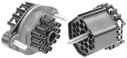
This is a picture of the 22-conductor bulkhead weather-PAC connectors. The part on the left is the bulkhead fitting, it will be mounted in the firewall, allowing the wiring to pass through the firewall, protected and sealed against the elements. The right side piece attached to the bulkhead fitting and is secured to it by a screw, which passes through the center of the fitting and into a threaded part on the bulkhead fitting. Now if the engine has to be removed, simply unplug the connector and pull it out.
Two (2) conductor weather-PAC connector
Four (4) conductor square Weather-PAC connector
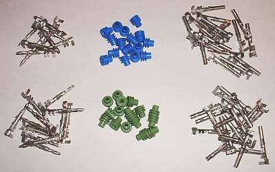
Male and Fe-Male pins along with 16-14ga green seals and 12ga blue seals. The wires are attached to the pins and the pins are inserted into the connector housing. The seals seal out the weather, dirt and dust from behind the wires.
How do You Make a Weather-Pac connector?
LIST OF AVAILABLE COLORS AND WIRE GAUGES
No wire smaller than 18 gauge should be used on any system or sub-system on a project like this. This in no way limits you, there are plenty of different colors available in sizes 18 gauge and larger that can handle your needs.
Chose the right type of wire. It needs to be Automotive Primary Wire, a wire that is compatible with the intended environment. 100% copper strands with a Polyvinyl insulation, rated at 12 volts and good for operating in temperatures between -29°F and 194°F. The jacket or insulation is highly resistant to grease, oil, acids and meets or exceeds S.A.E. specifications J1128, Ford MiL56A and Chrysler MS 3450.
Again as always, shop around to find the best prices on the wire you are going to need. There are several great places to purchase wire, and if you compile your list accurately, you will be able to save by buying in one large purchase. I like to buy 100 foot rolls, the smaller rolls are not well suited for a project like this. Most people end up needing two to three times as much wire as they originally thought. They simply under-estimated the amount of wire the project would take, and in the end ended up paying for their mistake. Sit down and list out all the circuits you have, as we did earlier. I'm sure no one would have thought we needed 143 different circuits just to satisfy the three (3) listed systems!
The following is a list of wire sizes and colors that was available to me when I was figuring out my wiring situation. Of course I could get additional colors as needed, but this is what I had to start working with. I always assume when working with DC circuits, that I will make all power connections COLORED=(+) and BLACK=(-). This does not mean that I can not use that color or black in a harness for some other reason, many manufacturers use colored and black wires in cables for reasons other than power circuits. It just means that when there is a power connection to be made, I will always use a COLORED wire for the positive(+) side and a BLACK wire for the negative(-) side.
18 GAUGE
RED - Innovate Pressure Sensors Common (3 wire circuit)
BLACK - Innovate pressure Senders Common (3 wire circuit)
WHITE - Innovate Oil Pressure Sendor
BLUE - Innovate Fuel Pressure Sendor
GREEN - Innovate Temperature Common (2 wire circuit)
ORANGE - Innovate Inter-cooler Temperature
YELLOW - Innovate Transmission Temperature
GREY - Innovate Fuel Temperature
PURPLE- Dakota Gear Light
16 GAUGE
RED - Innovate Throttle Position Switch
BLACK - Innovate Throttle Position Switch
BLUE - Dakota Dimmer Adjustment
WHITE -
GREEN -
ORANGE - Dakota Digital Speed Sensor
YELLOW - Dakota Digital Fuel Sender
GREY - Dakota Digital Engine Coolant Temperature
PURPLE - Dakota Digital Oil Pressure
14 GAUGE
RED- Dakota Power Connection (+)
BLACK
BLUE - Inovate Power Connection (+)
WHITE - Interior Lighting Power (+)
GREEN - Power Seat Power (+)
ORANGE - Heated Seat Power (+)
YELLOW - Power Windows Power (+)
GREY -
PURPLE- Remote Amp Switch (+) from Radio
12 GAUGE
RED - Ignition Power (+)
BLACK - Air Conditioning Power (+)
BLUE - High Beam Headlights (+)
WHITE - Low Beam Headlights (+)
GREEN - Engine Coolant Cooling Fan (+)
ORANGE - Turning Signals Power (+)
YELLOW - Inter-cooler Cooling Fan (+)
GREY - Back-up Lights Power (+)
PURPLE - Transmission Cooling Fan (+)
10 GAUGE
RED - EEC V Power Feed (+)
BLACK
BLUE
WHITE
GREEN
8 GAUGE
RED - Fuse Panel Feed (+)
BLACK - Fuse Panel Ground
BLUE - Alternator Feed (+)
WHITE
GREEN
ORANGE - Switched Fuse Panel Feed (+)
#2
RED - Amplifier feed (+)
BLACK - Amplifier Ground
#1
RED
BLACK
#1/0
RED - Starter Motor Feed (+)
BLACK- Main Engine ground
COOLING SYSTEM
Engine Coolant Electric Fan
12 Volt (+):#12 gauge wire to fuse panel12 Volt (-):#12 gauge wire to ground(battery)
Thermal Switch
Relay
Automatic Transmission Electric Fan
12 Volt (+):#12 gauge wire to fuse panel
12 Volt (-):#12 gauge wire to ground(battery)
Thermal Switch
Relay
Inter-cooler Electric Fan
12 Volt (+):#12 gauge wire to fuse panel
12 Volt (-): #12 gauge wire to ground(battery)
Thermal Switch
Relay
Inter-cooler Circulation Pump
12 Volt (+):#12 gauge wire to fuse panel
12 Volt (-):#12 gauge wire to ground(battery)
Thermal Switch
Relay
BRAKING SYSTEM
Stop Light Circuit
12 Volt (+):#14 gauge wire to fuse panel
12 Volt (-):#14 gauge wire to ground(battery)
Line lock circuit
12 Volt (+):#14 gauge wire to fuse panel
12 Volt (-):#14 gauge wire to ground(battery)
Brake Light Switch
TURNING SIGNAL SYSTEM
Right & Left Turning Circuit
12 Volt (+):#14 gauge wire to fuse panel
12 Volt (-):#14 gauge wire to ground(battery)
Self-canceling Turning Signal Switch-Steering Column Mounted
Flasher
Emergency Flashers
INTERIOR LIGHTS
12 Volt (+): #14 gauge wire to fuse panel
12 Volt (-): #14 gauge wire to ground(battery)
Courtesy Lights
Dome Lights
Door Switches
Dome Light Switch
HEADLIGHTS
Low Beam 12 Volt (+): #12 gauge wire to Battery
12 Volt (-): #12 gauge wire to ground(battery)
High Beam 12 Volt (+): #12 gauge wire to Battery12 Volt (-): #12 gauge wire to ground(battery)
Head Light Low Beam Relay
Low Beam Circuit
Head Light High Beam Relay
High Beam Circuit
High Beam Indicator
AIR CONDITIONING AND HEATER SYSTEM
AC Compressor Circuit
12 Volt (+): #14 gauge wire to fuse panel12 Volt (-): #14 gauge wire to ground(battery)
Blower Circuit
12 Volt (+): #14 gauge wire to fuse panel12 Volt (-): #14 gauge wire to ground(battery)
Control Circuit
12 Volt (+): #14 gauge wire to fuse panel12 Volt (-): #14 gauge wire to ground(battery)
STARTING SYSTEM
High Draw Starting Circuit
12 Volts (+) Red # 1 Gauge Wire
Neutral Safety Switch
Starting Circuit
12 Volt (+) #12 Gauge Wire
Accessory Circuit
12 Volt (+) #12 Gauge Wire
SEATING SYSTEM
Power Seats
12 Volt (+): Green #14 gauge wire to fuse panel12 Volt (-): Black #14 gauge wire to ground(battery)
Heated Seats
12 Volt (+): Orange #14 gauge wire to fuse panel12 Volt (-): Black #14 gauge wire to ground(battery)
AUDIO SYSTEM
RADIO
12 Volt (+): Red #14 gauge wire to fuse panel
12 Volt (-): Black #14 gauge wire to ground(battery)
Blue: 16 gauge wire for remote power switch
Orange: 16 gauge wire for non-switched power
Audio Input: R-L channel from CD Player 1 cable
Audio Output: RF- RR To Power Amplifier 2-cables
LF- LR To Power Amplifier 2-cables
Video Input: Rear View Camera 1 cable
Video Output: To Monitor 1 cable
Power Amplifier 5-channel
12 Volt (+): Red #1 gauge wire to battery
12 Volt (-): Black #1 gauge wire to ground(battery)
Remote power switch: Blue #16 gauge wire
Audio Input: 2-2 channel cables
Audio Output
Right Front Speaker : 2-#12 gauge wires
Left Front Speaker : 2-#12 gauge wires
Right Rear Speaker: 2-#12 gauge wires
Left Rear Speaker : 2-#12 gauge wires
Bass Speaker : 2-#12 wires
Remote CD Changer
12 volt(+): #14 gauge wire to fuse block
12 volt (-): # 14 gauge wire to chassis ground
Audio Output: 1-2 channel cable
Navigational System
Satellite Antenna: 1 cable