The
Ford Flathead
Engine
Project: Flat-Head
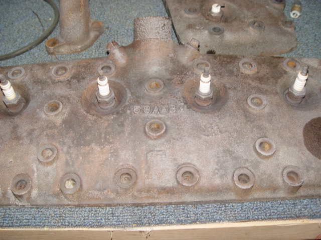
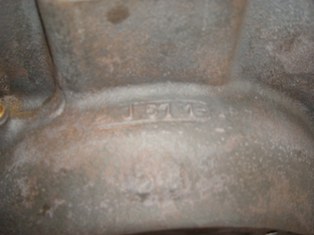
Identifying Our Engine, And A Little History
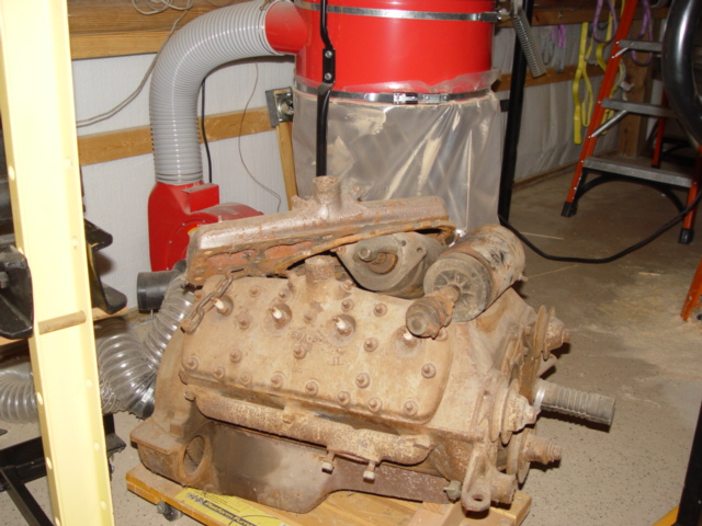
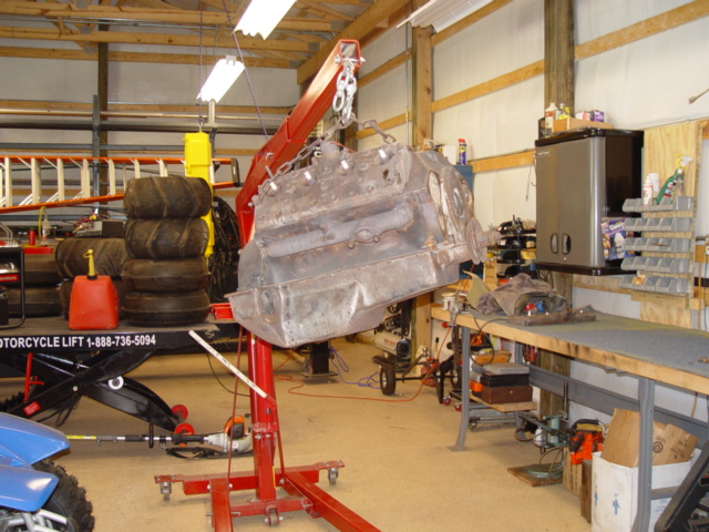
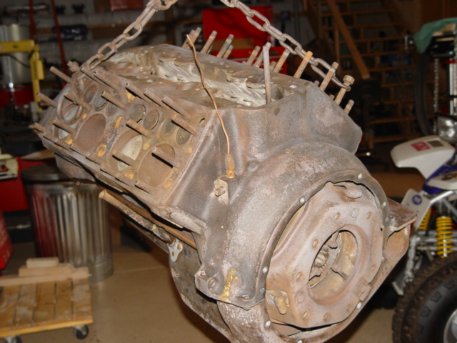
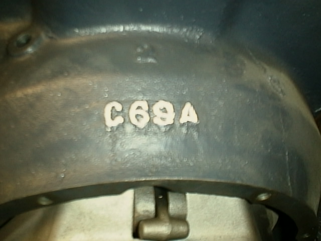
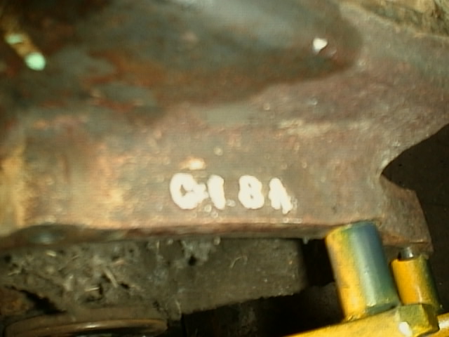
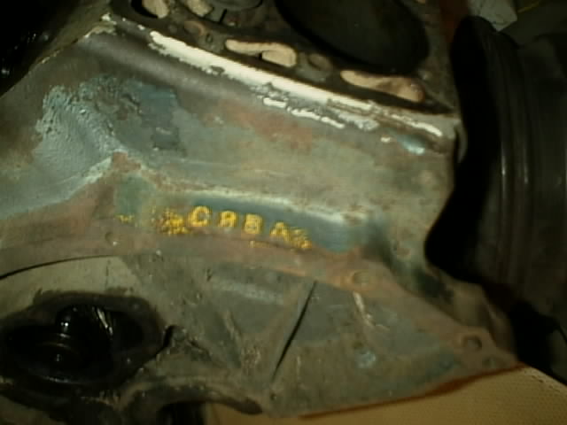
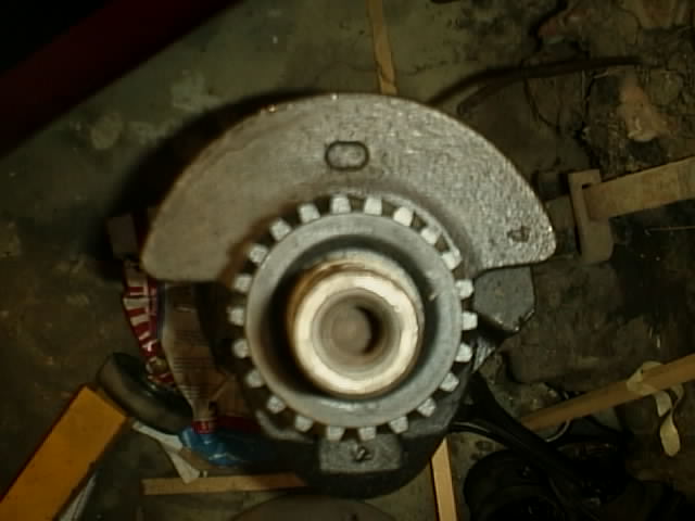
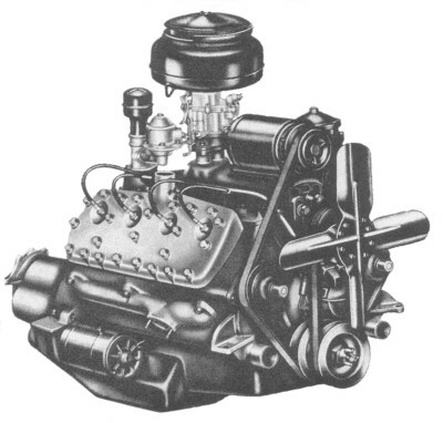
This is our Ford Flathead,
just as it looked right after we removed it from the '33. While not exactly a diamond in the rough, it is a sound and
complete example of what a Flathead Engine is and how they usually look when you find one.
To start out with, we acquired our
Flathead Engine when we decided to restore our 1933 Ford Tudor Sedan. The engine wasn't to
be reused in the restoration, instead it was replaced by the modern 4.6L Modular Engine Ford now produces in many of it's
new cars. These Engines were first put into production in 1994, and at first were anything but powerful. Truth is the 5.0L
that they were replacing had more horsepower then the new 4.6L Ford was releasing, and you can guess the feeling fellow Ford
lovers had. Why would anyone want a new engine that produces less horse power then the current (5.0L) model? Especially when
they were releasing this engine in there sports car line, the Ford Mustang. Eventually Ford began increasing the output of
there new engines, and it wasn't too long before the little 4.6L was making some good horsepower. I go over this because
the 1933 engine was very similar, this model year was also the first release of Fords new engine, the V-8 Flat-Head.
It, just like the 4.6L, had many teething problems that were eventually worked out and allowed the V-8 Flat-Head
to go on and become one of the most famous little engines Ford ever built. This new then engine, was the class of the Field.
With more torque and horsepower then anything else on the market, that is anything the average man could afford!. This was
made ever so popular by John Dillinger, he bought a 1933 Tudor sedan as his get-a-way car and was able to out-run all the
cops. He even sent Ford a letter thanking him for producing such a nice and fast car. While Mr. Dillinger was eventually cough,
he helped make the point about V-8 power and the two became famous.

The Flathead
was produced all the way up until the 1954 model year. Then Ford in a race with Chevrolet, Dodge and other automobile manufacturers,
started producing the Ford "Y" Block, Over-Head Valve Engines. In it's 21 year run, it was constantly fine tuned
till the Flathead became darn near bullet proof as it neared it's final years of production. Even today, the Flathead
is considered to be "The Engine" by many true Hot Rodders, for anything V-8 powered, especially for the early Ford
cars and trucks.
Project COBRA'33 was not designed to use such an
engine, this car was to be the pinnacle of Old meets New. In so, I wanted to merge the classic old lines of one of Americas
best looking sedans with the raw power and convenience that all of today has to offer. The style of the thirties is long gone,
but if it were around today, this is what they might be offering to the public. Who knows, there is a very strong segment
of retro styling going on now, the old Camaro, Mustang and Challenger are all making a comeback, so who is to say the next
HOT old ideal might be to re-live the thirties?? There is definitely a very large and effluent population segment that would
surely like to re-live their past with just such a car or truck!! Project
COBRA'33 has the latest of suspension systems, with a highly appointed Independent Front Suspension by Heidt.
Along with a sophisticated 4-bar setup in the rear with Coil/Over Shocks and a Anti-Sway Bar. This type suspension allows
comfortable cruising and aggressive cornering, all in one package.
MY GOALS
Project: Flat-Head
is first and foremost just an exercise to explore the limits and limitations of
modernizing the Flat-Head Engine. From the very start, I intend to, with as
much realization as possible, change our Flat-Head Engine into a Modern, Twin
Turbo-Charged, Electronic Fuel Injected representation of what someone might or could do. This engine, although real, is not
going to be a working engine when it is finished. Instead, this Flat-Head
Engine will become a conversation piece, a Table, and hopefully a work of Modern Automotive Art. Yes I will be using all real
parts, our Flat-Head is real, the Turbo-Chargers will be new, real and functional,
the Inter-Coolers will also be new, real and functional, as will everything else, but the final product will not be a running
engine, instead it will be a representation of what someone could do based on what someone else has done.
I'm very excited about Project:Flathead, this is something new for me, and I'm hoping others
like your self's will like it as well.
The following is another article we printed
from the Mega Squirt web site. This and many other useful topics are available at www.sdsefi.com
Intelligent Engine Modifications
With so much misinformation
and BS out there in the performance aftermarket world, we have decided to offer the reader some real tips based on 20 years
of performance engine building and turbocharging experience.
Street or Race?
This is probably the biggest question related
to successful mods and the most often ignored. Many people just don't understand why you can't drive a race spec engine
on the street. Let's examine the differences in the 2 different worlds:
Street
A good street engine should
have a smooth idle, have lots of low end torque, a wide power-band, long life and good fuel economy. To get these characteristics,
most street engines have relatively moderate camshaft timing, small turbos, small diameter intake ports with long runners
and usually cast pistons. They are designed to run on gasoline with an octane rating of 87 to 92 RON in most cases and usually
produce less than 100 hp/liter in naturally aspirated form and 120 hp/liter in turbocharged form
Race
Ideally, a good race engine
should have all of the same characteristics that the street engine has above but since high power output is one of the primary
concerns, many compromises in those other desirable traits must be made to achieve this power level. To achieve higher power,
ports are opened up for increased flow at high rpm and camshaft timing and lifts are increased, both of which kill off low
rpm torque, power, fuel economy and that smooth idle.
The rpm capabilities are upped to permit higher airflow rates. This is usually done by changing to stronger
parts such as connecting rods, pistons, crankshafts and valve springs. If the engine is turbocharged, a larger turbo and inter-cooler
along with forged pistons and stronger rods are fitted to handle the loads. Raising the red-line will not make any more power
in most cases unless the engine components are modified to efficiently pass that increased airflow.
On naturally aspirated engines, the compression
ratio is often raised substantially to boost torque and power. This is possible when using high octane race fuel. On turbo
engines, the compression ratio may either be raised or lowered depending upon fuel octane allowed, maximum boost pressure
and possible fuel limits for the race.
As you can see, the two engines vary considerably in requirements and execution. The problem comes in when
someone wishes to increase the power output of a street driven engine beyond reasonable limits while expecting no major degradation
in "street-able" qualities.
Naturally Aspirated Engines for the Street
On most engines for street use,
there are only a few ways to substantially increase airflow and thus power.
Porting the head will improve airflow if done correctly. If the
ports and runners are enlarged greatly, low speed torque will suffer considerably.
Higher duration and lift cams are the main modification for increasing
power. The more duration and valve overlap a cam has generally, the worse the low end torque, fuel economy and idle will be.
Of course, top end power should be better. On most 4 cylinder engines, going with more than 285 degrees of duration at 0 lift
will result in truly gutless bottom end power. With too much cam, the effective power-band becomes so narrow that the car
is just plain miserable to drive in traffic. Most street engines spend the majority of their time in the 2000-4500 rpm range.
Engines which are heavily cammed may not begin to produce substantial gains until above 4500 rpm and you are paying for this
95% of the time while being able to enjoy that top end only 5% of the time. We see more problems and complaints with people fitting race type cams in street type
engines. It makes the EFI hard to tune and the car annoying to drive in many cases. Don't over cam!
Increasing the compression
ratio is another way to increase power. It also increases fuel mileage. Unfortunately, the pump fuel available in most areas
limits the compression ratio usable on the street to under 10.5 to 1 on most engines. The difference in power is minimal going
from say 9 to 10.5 to 1 and it is a lot of work to shave the head or install new pistons. Again, if you get stupid and try
to run an 12 to 1 CR on 92 octane fuel, you will suffer with lots of pinging and eventual failure. Many high compression street
engines must have their timing severely retarded to avoid detonation which reduces the power right back to stock levels. Don't raise the compression ratio too high!
Raising the red-line to achieve higher airflow through the engine
is another way of increasing power. To do this effectively, you will likely need to install a hotter cam with stiffer valve
springs, port the head and possibly install stronger bottom end parts like connecting rods. The factory red-line is there
for a reason. If you exceed it repeatedly by a large margin, you may eventually have a catastrophic failure.
Installing a header and free
flowing exhaust along with a cold air induction system may free up a few more hp on certain engines. Don't expect gains
of over 10% with these mods on most engines.
Nitrous oxide injection is used quite extensively in drag racing for a substantial power gain. When adding
large amounts of nitrous, engine components may have to be upgraded to withstand the higher pressures involved. This is not
usually a great mod for street use as everything must be just right as far as fuel and nitrous flow goes and of course the
major disadvantage is that the tank runs dry after only a few minutes of use and must be refilled.
Conclusion
On street driven Atmospheric
engines, there are minimal gains to be had on most small engines without sacrificing a lot of drive-ability. If you need more
power, you need a larger engine usually. Expecting your 18 second car to do 13 seconds while retaining good idle and fuel
economy when modified is unrealistic most of the time.
Turbocharged Engines for the Street
Turbos are a different ball
of wax but many of the same mistakes are made when modifying them. Most of the same power increasing methods from above can
also be applied to turbo engines. Because turbo engines usually have lower compression ratios than Atmospheric engines, they
do not take kindly to hot cams on the street. The gain in top end will almost always be offset by a huge loss in the lower
power-band and more turbo lag. Stock cams are the way to go on most turbo street engines. Don't waste your money on so
called "turbo cams" for 4 and 6 cylinder engines. These may boost economy slightly but they almost always lose power.
Most of these were designed by guesswork rather than by actual turbo experience. 4 Valve engines in general when turbocharged
do not need hotter cams for the street.
Porting a turbo head will make the same type of gains as on an Atmospheric head despite what some people
say. You can make the same power with less boost or more power with the same boost.
To obtain higher than stock outputs, the compression ratio should
be LOWERED on a street turbo. This will permit higher boost with optimized timing on low octane fuel. Forged pistons are an
excellent idea on turbos as they have 2-3 times the strength and heat dissipation of cast pistons. Forged connecting rods,
colder spark plugs and stronger head gaskets are also recommended.
Stock turbos are usually sized for mid range torque and are undersized
even for stock top end power. Compressor and turbine size upgrades are needed to realize substantial power gains. Going too
large on turbos will lead to poor low end response. Turbos need to be properly matched for the application and primary intended
usage. A couple of rules of thumb can be used if you have access to a compressor map. HP X 1.62 = airflow in CFM, HP divided
by 8.07 = airflow in lbs./min. Avoid matching for efficiencies of under 65% at full power and operation near the surge line
also.
Inter-cooling
is extremely important. Stock inter-coolers with a few exceptions are total crap when used for performance application's
offer low efficiencies and high pressure drop. Install a properly matched core from Spearco. The closer that your charge temperature
is to the ambient temperature, the higher the HP potential will be.
Finally, boost pressures can be raised to increase engine airflow
and power. This can only be done within the limitations of the fuel octane rating and ignition timing. Read the other tech
articles relating to combustion and fuel for a better understanding. In any case, running 20 psi on the street is relatively
meaningless. High boost pressure does not necessarily mean high HP. If you are running this kind of boost on the street, you
probably have a host of mismatched or restrictive parts on your engine. With properly matched components and an efficient
inter-cooler, one rarely needs to exceed 15 psi on the street. With these in place, you will be at the safe mechanical limits
of most stock based engines and HP will be doubled or tripled over stock. Check out some of the cars on our project page prepared
at Racetech if you don't believe this. Since engine life will plummet once you exceed this type of output, it is not a
viable option for most people to be rebuilding an engine every 10,000 miles. You don't have a street-able engine in my
opinion at this point.
Conclusion
Power may be increased substantially through turbocharging on the street
but reliability will suffer unless it is applied correctly.
Turbo Race Engines
I will use a Toyota 2TC engine which I
prepared for road racing use a few years ago as an example of what can be done with properly applied engine modifications
and turbocharging. The stock engine starts out as a 1588cc, 2 valve per cylinder, push-rod, cross-flow Hemi. The stock hp
is rated at 70 at 6000 rpm.
The block was bored out from 85mm to 88mm to fit Mahle VW forged pistons. This mod brings the displacement
out to 1702cc and drops the compression ratio from 8.6 to 7.2 to 1. The rest of the block is totally stock as is the crankshaft.
The connecting rods were polished
and shot-peen-ed. They were converted to a full floating pin arrangement to suit the new pistons and Ford SPS big block bolts
were fitted to withstand the higher anticipated rpms.
The camshaft selected was the same cam we used on our race Atmospheric 2T engines with .430 valve lift/ 284/222
degrees duration at 0 and .050 lift respectively on 108 degree lobe centers. Valves were enlarged from 41 to 44.5mm on the
intake via Ford 6 cylinder ones and from 36 to 38mm via Nissan 200SX ones. The head was extensively ported on the flow bench
taking intake flow from 82 to 122 cfm and the exhaust from 66 to 86 cfm. Valve guides were shortened and bronze bushed for
increased flow and heat dissipation. Exhaust seats were widened to .080 for better heat transfer. Norris triple valve springs
and aluminum retainers were also used.
A stock oil pump was used and an HKS 1mm metal head gasket was fitted.
On the externals; A custom, equal length header was made using
1.625 inch ID thick walled tubing , a custom intake manifold was made fitted with a 70mm Mercedes throttle body and eight
Bosch 490cc injectors. The turbo was a Garrett TO4 with H-3 compressor and a .58 turbine. This blew through a massive Spearco
inter-cooler measuring 17 X 21 X 3 inches and 2.5 inch mandrel bent tubing. The exhaust was 3 inch mandrel bent tubing open.
Fuel was M-85.
This
engine produced 358hp at 7700 rpm at only 15 psi boost. The stock hp was quintupled! Engine life was approximately 6 hours
at this power level and about 15 hours at 12 psi and 310hp. Eventually, the main bearing caps cracked from the power output
but this was caught before major damage occurred. The effective power-band was 5000 up. Red-line was limited to 7700 rpm mainly
for valve-train longevity although hp was still increasing at this point. This engine was used for road racing so the life
expectancy had to be about a full season or 15 hours.
Conclusion
Turbocharged race engines can produce staggering hp numbers given
strong enough parts however engine life goes down as power is increased. A narrow power-band may be acceptable on a race engine
because close ratio gearboxes are usually fitted to minimize rpm drop between shifts.
There seems to be two types of people preparing turbo race engines
for import drag racing. One school uses small, stock based turbos for quick spool up. These engines run super high boost but
don't make any power. School two fits turbos which are way too large. These have poor turbo response and a super narrow
power-band. They produce very high hp across only 1000 rpm on the top end and as a result are not very quick. Bigger turbos
don't necessarily mean quicker times. Turbos must be properly matched on the compressor as well as the turbine end.
Some people really know what
they are doing and some don't. 450 hp out of a 16 valve 1900cc Acura drag motor at 25 psi is just not impressive when
years ago Jack Roush was producing in excess of 700 hp out of 8 valve 2.3 and 2.5 liter Ford Pinto engines for road racing
events running from 2 to 24 hours.
Engine Displacement
For street use, you want as many cubic
inches as you can get. Torque on the street is king. Always go for as many cubes as you can if you have a choice of engines.
Performance
EFI Considerations
When increasing airflow through your engine for more power, you must also increase fuel flow to match. At
some point, the stock injectors and possibly fuel pump will not supply enough fuel. Larger injectors will have to be fitted.
As soon as you do this with the stock ECU, the engine will no longer run properly. You will have to either re-chip or install
a different EFI system.
If
your engine uses a vane type airflow meter, you are losing a substantial amount of power potential through its restriction.
It is foolish to spend a lot of time and money improving engine airflow, then strangling it with a door type meter on the
front. Engines fitted with this type of meter will usually gain at least 10% when changed to a large hot wire or speed/density
type system. It is important to note that when the airflow flap bottoms out at high airflow rates, it is no longer capable
of sending a proper signal to the ECU. The fuel mixture will no longer be correct.
Some companies offer rising rate fuel pressure regulators with
their turbo kits to allow increased injector flow rate over stock pressure. Instead of adding 1 psi of fuel pressure per psi
of boost as in a conventional FPR, they will ramp up at 2-5 psi per psi of boost. Some of these work OK at low boost but the
fuel delivery curve is now in the hands of a mechanical device, not the ECU. This is crude at best. It takes 4 times the fuel
pressure to double the fuel flow. If your stock fuel pressure is 45 psi, you will need 180 psi to double your fuel flow.
Two things happen here.
First, many injectors become non-linear in fuel delivery above 60-70 psi differential or may not even open, leading to a possible
lean out condition under boost. Secondly, the fuel pump is not designed to do this. It either can't produce the pressure
or volume needed or will burn out quickly due to the massive increase in current draw. These are a bad idea at high boost
pressures.
Conclusion
Use the right tool for the job. You don't normally use pliers to turn a screw in. It works, but not well.
The same thing goes for performance EFI applications. Sure, you can trick an old L-Jetronic system with a resistor on the
water temp input and get some more fuel out of the system but the method has serious limitations past a point and will not
really supply the correct mixture across the operating range.
Courtesy
of SDSEFI.com