|
|
 |
|
|
 |
DESCRIPTION AND OPERATION Engine
The 4.6L (4V) (281 CID) Cobra Engine is a V-8 with the following
features: - Intercooled
Supercharger
- Dual Overhead Camshafts
- Four Valves
Per Cylinder
- Sequential Multiport Fuel Injection (SFI)
- An
Aluminum Intake Manifold
- Aluminum Cylinder Heads
- A
Cast Iron, 90-degree V- Cylinder Block
- Individually Chain-Driven Camshafts with a Hydraulic
Timing Chain Tensioner on each Timing Chain
- The Electronic Ignition System with Eight
Ignition Coils
Identification
Always refer to these labels when replacement parts are necessary or when checking engine calibrations. The engine parts often
differ within a CID family. Verification of the identification codes will ensure that the correct parts are obtained. These
codes contain all the pertinent information relating to the dates, optional equipment and revisions. The Ford Master Parts
Catalog contains a complete listing of the codes and their application.
Code Information
The engine code information label, located
on the side of the valve cover and the front side of the valve cover, contains the following:
- Engine plant code
- Engine code
- Engine
Build Date
Exhaust Emission Control System
Operation and necessary
maintenance of the exhaust emission control devices used on this engine is covered in the Powertrain Control/Emissions Diagnosis
(PC/ED) manual.
Induction System
The sequential multiport fuel injection (SFI) provides the fuel/air mixture needed
for combustion in the cylinders. The eight solenoid-operated fuel injectors:
- Are mounted in
the lower intake manifold.
- Meter fuel into the air intake stream in accordance with engine
demand.
- Are positioned so that their tips direct fuel just ahead of the engine intake
valves.
- Are connected in series with the fuel pressure sensor.
- Supply fuel from the fuel tank with a fuel pump mounted in the fuel tank.
- Meter fuel into the air intake stream in accordance with engine demand.
- Are
positioned so that their tips direct fuel just ahead of the engine intake valves.
- Are
connected in series with the fuel pressure sensor.
- Supply fuel from the fuel tank with
a fuel pump mounted in the fuel tank.
A constant fuel pressure drop is maintained across the fuel injectors
by the fuel pressure sensor. The fuel pressure sensor:
- Is positioned upstream from the fuel injectors on the fuel injection supply manifold.
Valve Train
The valve
train operates as follows:
- The
inner rotor is piloted on the crankshaft post and is driven through flats on the crankshaft.
- System pressure is limited by an integral, internally-vented relief
valve which directs the bypassed oil back to the inlet side of the oil pump.
- Oil pump
displacement has been selected to provide adequate volume to ensure correct oil pressure both at hot idle and maximum speed.
- The relief valve calibration protects the system from excessive pressure during high
viscosity conditions.
- The relief valve is designed to provide adequate connecting rod
bearing lubrication under high-temperature and high-speed conditions
- Ball-tip hydraulic
lash adjusters provide automatic lash adjustment.
- Roller followers ride on the camshaft
lobes, transferring the up-and-down motion of the camshafts to the valves in the cylinder heads.
Positive Crankcase Ventilation System
All engines are equipped with a closed-type positive crankcase
ventilation system recycling the crankcase vapors to the upper intake manifold.
Lubrication System
The engine lubrication system operates as follows:
- Oil is drawn into the oil pump through the oil pump screen cover and tube in the sump of the oil pan.
- Oil is pumped through the oil bypass filter on the left front side of the cylinder block.
- Oil enters the main oil gallery where it is distributed to the crankshaft main journals both cylinder heads.
- From the main journals, the oil is routed through cross-drilled
passages in the crankshaft to lubricate the connecting rod bearings. Controlled leakage through the crankshaft main bearings
and connecting rod bearings is slung radially outward to cool and lubricate the cylinder walls as well as the entire connecting
rod, piston and piston rings assembly.
- The left cylinder head is fed from a drilling into the supply passage feeding the main gallery at the front
of the cylinder block. The right cylinder head is fed from a drilling into the rear of the main gallery. Main gallery
pressure is reduced as it enters the cylinder head galleries through fixed serviceable orifices located at the upper part
of the feed passages. It is this reduced pressure in the cylinder head galleries which feeds the camshaft journals, the hydraulic
lash adjusters and the primary and secondary timing chain tensioners.
- The camshaft lobe
and roller followers are lubricated by splash created through valve train operation.
Cooling System
The engine cooling system includes the following:
- Radiator
- Water
pump
- The electric cooling fan motor and fan blade, activated by the variable control
module
- The degas bottle, which aids in maintaining the correct volume of engine coolant
- Water thermostat
- Upper radiator hose
- Lower radiator hose
- Heater water hoses
Drive Belt System
The 4.6L (4V) DOHC engine is equipped with a serpentine drive belt. To
ensure maximum life, a replacement drive belt should be of the same type as originally installed. The
accessories mounted on the front of the engine are belt-driven by the crankshaft. The serpentine
drive belt is routed over each accessory pulley, driven by the crankshaft pulley bolted to the crankshaft. ITEM | PART NUMBER | DESCRIPTION | 1 | 6F066 | Supercharger Assembly | 2 | N806154 | Screws
(2 req’d) | 3 | 9F715 | Idle Air Control Valve | 4 | - | Idle Air Control Valve Gasket | 5 | 9P697 | Spacer Assembly | 6 | 9E936 | Throttle
Body Gasket | 7 | 9E929 | Throttle Body | 8 | - | Bolts (4 req’d) | 9 | - | Bolts (2 req’d) | 10 | 9E926 | Throttle Position
Sensor | 11 | -N804178 | Nuts (4 req’d) | 12 | - | Studs (4 req’d) | 13 | - | Spacer Assembly gasket | 14 | -9D475 | Exhaust Gas Recirculation
Valve | 15 | - | Stud | 16 | 9D477 | Exhaust Gas Recirculation Tube | 17 | - | Manifold
Absolute Pressure Sensor | 18 | 9J460 | Differential Pressure Feedback EGR System | 19 | 9J459 | Exhaust Gas Recirculation Vacuum Regulator | 20 | 9J472 | Vacuum
Accessory Bracket |
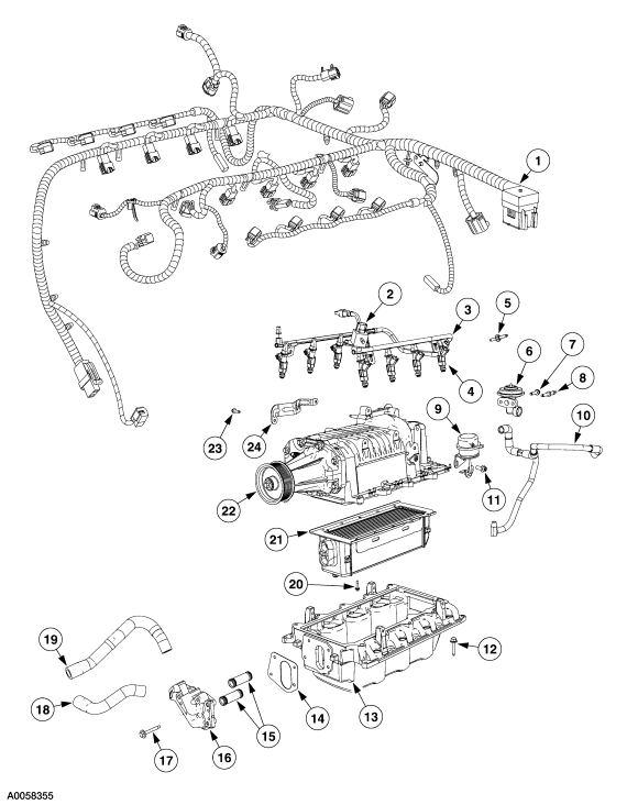
ITEM | PART
NUMBER | DESCRIPTION | 1 | 12B637 | Wiring Harness | 2 | 9C986 | Fuel Pulse Damper | 3 | 9F792 | Fuel
Injection Supply Manifold | 4 | 9F593 | Fuel Injector | 5 | - | Stud | 6 | 9D475 | Exhaust Gas Recirculation Valve | 7 | W701232 | Bolt | 8 | N806979 | Stud | 9 | - | EGR Vacuum
Hoses | 10 | 6F089 | Vacuum Actuator Valve | 11 | N605892 | Bolts (2 req’d) | 12 | - | Bolts 10 req’d) | 13 | 9J447 | Lower Intake Manifold | 14 | 9L438 | Coolant Intake Manifold
Gasket | 15 | - | Coolant Tubes | 16 | 9N491 | Coolant Intake Manifold | 17 | W701592 | Bolt | 18 | NL443 | Inter Cooler Hose | 19 | N1443 | Inter Cooler Hose | 20 | W506404 | Bolts
(10 req’d) | 21 | 6K755 | Charge Air Cooler | 22 | 6F066 | Supercharger Assembly | 23 | N605892 | Bolt | 24 | 9726 | Accelerator Cable Bracket |
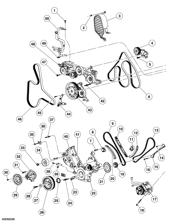 ITEM | PART NUMBER | DESCRIPTION | 1 | N605904 | Bolt | 2 | N620480 | Nut | 3 | 6A946 | Cover
| 4 | 17K814 | Alternator Bracket Assembly | 5 | N811268 | Bolts (2 req’d) | 6 | 8620 | Accessory Drive Belts | 7 | N606543 | Bolts (4 req’d) | 8 | 6L266 | Timing Chain Tensioner | 9 | 6268 | Timing
Chain (2 req’d) | 10 | 6M256 | Timing Chain Guide | 11 | 6L266 | Timing Chain Tensioner | 12 | 6L253 | Timing Chain Tensioner Arm | 13 | 6268 | Timing
Chain (2 req’d) | 14 | N804958 | Bolts (2 req’d) | 15 | 6B274 | Timing Chain Guide | 16 | N606527 | Bolt | 17 | 19D269 | AC Compressor | 18 | N806184 | Bolts (3 req’d) | 19 | 6306 | Crankshaft
Sprocket | 20 | 6L253 | Timing Chain Tensioner Arm | 21 | 12A227 | Ignition Pulse Ring | 22 | 6C086 | Engine Front Cover | 23 | N806177 | Bolts (8 req’d) | 24 | N806300 | Studs
(5 req’d) | 25 | 6700 | Crankshaft Front Seal | 26 | 6316 | Crankshaft Pulley | 27 | N806165 | Washer | 28 | W701512 | Stud | 29 | 8A5282 | Water Pump Pulley | 30 | N806282 | Botls (4 req’d) | 32 | 8501 | Water Pump | 33 | N808102 | Bolt | 34 | 19A216 | Belt
Idler Pulley | 35 | N804178 | Nut | 36 | N806300 | Harness Support Bracket | 37 | N806300 | Stud | 38 | N806155 | Bolt | 39 | 6C315 | Crankshaft Position Sensor | 40 | N806155 | Bolt | 41 | 6B288 | Camshaft
Position Sensor | 42 | B808920 | Bolts (3 req’d) | 43 | 6C254 | Crankshaft Extension Support Pulley | 44 | 10153 | Lower Support Bracket | 45 | N605909 | Bolts
2 (req’d) | 46 | 8620 | Accessory Drive Belt | 47 | N811268 | Bolt | 48 | 8B603 | Belt Idler Bracket Support | 49 | N808198 | Stud | 50 | 9N491 | Hose
and Tube Assembly |
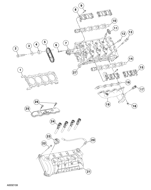
ITEM | PART NUMBER | DESCRIPTION | 1 | 6083 | Cylinder
Head Gasket | 2 | - | Bolt (2 req’d) | 3 | - | Washer (2 req’d0 | 4 | 6255 | Spacer | 5 | - | Secondary Timing Chain (2 req’d) | 6 | - | Screw
& Washer | 7 | 6C271 | Timing Chain Vibration Damper | 8 | 6B277 | Camshaft Bearing Cap | 9 | - | Bolt (24 req’d) | 10 | 6A271 | Canshaft | 11 | 6529 | Roller
Follower (8 req’d) | 12 | 6C501 | Hydraulic Lash Adjuster | 13 | 6065 | Bolt 20 req’d) | 14 | 6A273 | Camshaft | 15 | 6B278 | Camshaft Bearing Cap (2 req’d) | 16 | 9448 | Exhaust
Manifold Gasket | 17 | 9F485 | EGR Valve Tube to Manifold Connector | 18 | W701706 | Nut (8 req’d) | 19 | 9431 | Exhaust Manifold | 20 | 6C324 | PVC
Tube | 21 | 6A505 | Valve Cover | 22 | N808199 | Bolt (20 req’d) | 23 | 6766 | Oil Fill Cap | 24 | 12A366 | Ignition Coils | 25 | 6P068 | Ignition Coil Cover | 26 | N807309 | Bolt
(4 req’d) | 27 | 6050 | Cylinder head |
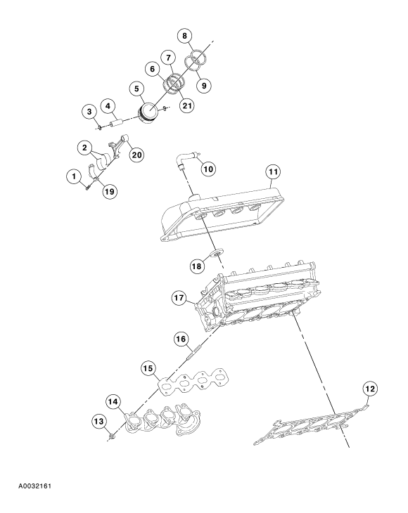 ITEM | PART NUMBER | DESCRIPTION | 1 | 6214 | Bolt (2 req’d) | 2 | 6211 | Connecting
Rod Bearing (16 req’d) | 3 | 6140 | Piston pin Retainer (16 req’d) | 4 | 6135 | Piston Pin (8 req’d) | 5 | 6110 | Piston
(8 req’d) | 6 | 6159 | Piston Ring (8 req’d) | 7 | 6159 | Piston Ring (8 req’d) | 8 | 6150 | Piston Ring (8 req’d) | 9 | 6152 | Piston
Ring (8 req’d) | 10 | 6758 | Crankcase Vent Tube & Connector | 11 | 6582 | Valve Cover | 12 | 6051 | Cylinder
Head gasket | 13 | W701706 | Nut (8 req’d) | 14 | 9430 | Exhaust Manifold | 15 | 9448 | Exhaust Manifold gasket | 16 | W701681 | Stud (8 Req’d) | 17 | 6049 | Cylinder
head | 18 | 6C527 | Spark Plug Gasket (8 req’d) | 19 | 6200 | Connecting Rod 98 req’d) | 20 | 6200 | Connecting
Rod (8 req’d) | 21 | 6161 | Piston Ring 98 req’d) |
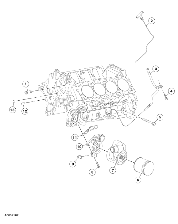
ITEM | PART NUMBER | DESCRIPTION | 1 | 8555 | Water By-Pass Tube | 2 | 6750 | Oil
Level Indicator | 3 | 6754 | Oil Level Indicator Tube | 4 | N806155 | Bolt | 5 | 6C358 | Bolt (10 Req’d) | 6 | 6714 | Oil Bypass Filter | 7 | 6A642 | Oil
Cooler | 8 | N806156 | Bolt (4 req’d) | 9 | 9278 | Oil Pressure Sender | 10 | 6884 | Oil Filter Adapter | 11 | 6A636 | Oil Filter Adapter
gasket | 12 | N620482 | Dowel | 13 | 87836 | Plug |
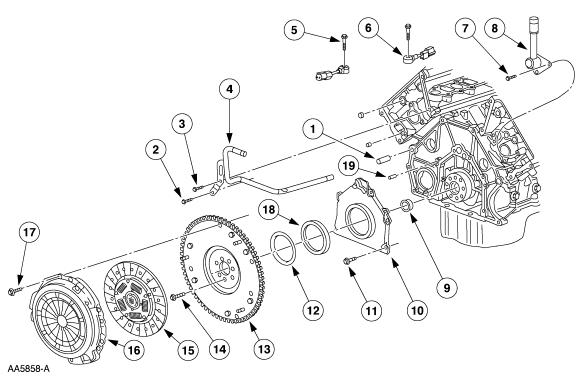 1 | N807198 | Dowel Pin (2
Req’d) | 2 | N807309 | Bolt | 3 | N807959 | Bolt | 4 | 18663 | Heater Water Hose | 5 | W500110 | Bolt (2 Req’d) | 6 | 12A699 | Knock Sensor (2 Req’d) | 7 | N807309 | Bolt
(2 req’d) | 8 | 18696 | Heater Water Hose | 9 | 7120 | Pilot Bearing | 10 | 6K318 | Crankshaft Rear Retainer | 11 | N806155 | Bolt
(6 req’d) | 12 | 6310 | Crankshaft oil Slinger | 13 | 6375 | Flywheel | 14 | N808139 | Bolt (8 Req’d) | 15 | 7550 | Clutch Disc | 16 | 7563 | Clutch
Pressure Plate | 17 | N808969 | Bolt (6 Req’d) | 18 | 6701 | Crankshaft Oil Seal | 19 | N806007 | Dowel Pin (2 Req’d) |
1 | N806177 | Bolt 94 Req’d) | 2 | N806459 | Dowel (4 Req’d) | 3 | 6A341 | Thrust Washer | 4 | 6303 | Crankshaft | 5 | 6A339 | Thrust
Bearing | 6 | 6325 | Main Bearing Cap (5 Req’d) | 7 | 6345 | Bolt (10 Req’d) | 8 | 6K25 | Main Bearing Cap (5 Req’d) | 9 | 6687 | Bolt
(10 Req’d) | 10 | N806180 | Spacer | 11 | N605904 | Bolt | 12 | 6710 | Oil Pan Gasket | 13 | 6675 | Oil Pan | 14 | W701240 | Bolt (16 Req’d) | 15 | 6622 | Oil Pump Screen Pickup&
Tube | 16 | N806155 | Bolt (2 Req’d) | 17 | N811280 | Spacer (3 req’d) | 18 | 6345 | Bolt (6 Req’d) | 19 | 6C360 | Main
Bering Cap Adjusting Screw (10 Req’d) | 20 | 6A338 | Crankshaft Main Bearing (4 Req’d) | 21 | N806201 | Woodruff
Key | 22 | 6621 | Oil Pump | 23 | N806183 | Bolt (4 Req’d) | 24 | 6333 | Crankshaft Main Bearing | 25 | 8501 | Water Pump |
|
 |
|
Enter content here
|
 |
|
Enter content here
|
 |
|
Enter content here
|
|
|
Enter supporting content here
Pro Weld
5937 Ethan Drive
Burlington, KY 41005
859-586-4069
Proweld@myway.com
|
|
|
 |

