|
|
 |
|
Enter subhead content here
|
|
The Ford Flathead Engine 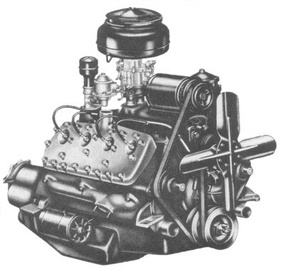
The Dis-Assembly
07-21-08
Today we began Project: Flat-Head ,
this is a project within a project. As you might or might not know, we are building Project COBRA'33,
a 1933 Tudor Sedan that will be fully up-dated with all of the offerings of today. The engine from this project is how
we started on Project:Flathead
. 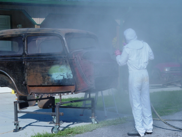
This is Doug,
he owns "What-A-Blast" a portable Sand-Blasting Company that serves those in the Greater Cincinnati area.
We had him Soda-Blast the '33 and many of the sheet metal parts, he also blasted the Flathead Engine to remove the many
years of dirt and grim.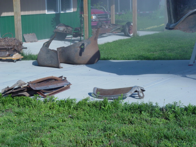
These are the many
parts we also had blasted. While we are going to sell most of them, I had them blasted anyway to remove the dirt and
rust. This makes them easier to handle and hopefully more valuable. We started by having the guys at "What-A-Blast"
sand blast the engine block and it's cylinder heads. This cleaned off the dirt and rust that accumulated over the
many years the engine sat in storage. While we will still have to do much more cleaning, it's a great start.
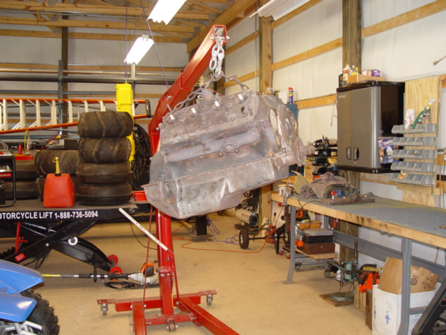
This
is our newly Blasted Engine, sure makes a difference doesn't it?? Now we can start the dis-assembly.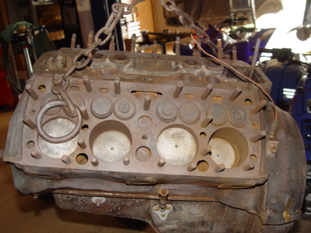
This is the
side (Drivers) that had the Cylinder Head removed and left off some 40+ years ago. It's also the side that had the
problem. Notice how clean the Engine is! One of the cylinder heads have been off for at least the last 40 years. This has seriously
rusted the one side of the engine and it's cylinder walls. We will have to pay extra attention to that side as we
go about the dis-assembly process. The first thing I did was to prep the dis-assembly by spraying every bolt and nut
with penetrating oil, several times. This seemed to work, for the dis-assemble was quite easy. Directly after
the sand blasting, we picked the engine up with a lift, and began work. First off was the front water pumps, they were
easy and took no time. Next up, the oil pan. I would have never thought it would still be full of oil, but it
was. Good thing I also use a drip/oil pan, cause we needed it, there was at least 4 quarts of oil inside. The
oil pan was very easy to remove, but also brought to life the big dent in it's bottom. No doubt the work of some
rookie who jacked the car up by the oil pan, well tackle getting those dents out latter. 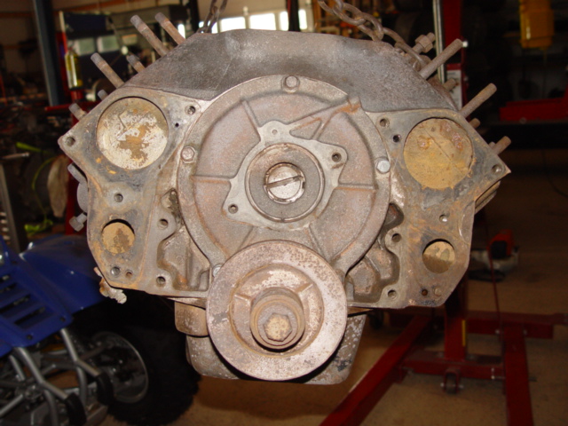
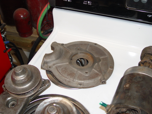
Here
we see the front of the Flathead. The two(2) Water Pumps have been removed, as well as both Heads. The next step
is to remove the Oil Pan, then the Front Pulley and the Front Cover. The bottom end was in perfect condition, there was some sludge in the pan, but not alot
and everything else looked great. The UN-touched cylinder head was next to come off, so far so good, that pre-oiling
sure pays dividends! Now we disassemble the distributor, front cover, vent tube, Front Pulley, timing gears and everything
come right off. We needed a Puller to remove the Front Pulley, but with the right tools, it wasn't a problem. The
original fiber timing gears are in perfect condition, know wear marks or anything that might suggest this engine was in need
of repair.
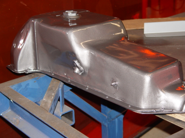
This
is the Engine Oil Pan, while it looks to be in very good shape in this picture, there is a huge dent in the bottom that can
not been seen.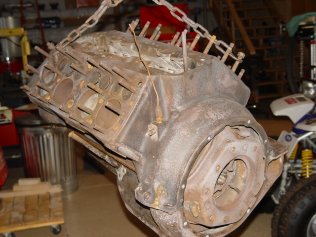
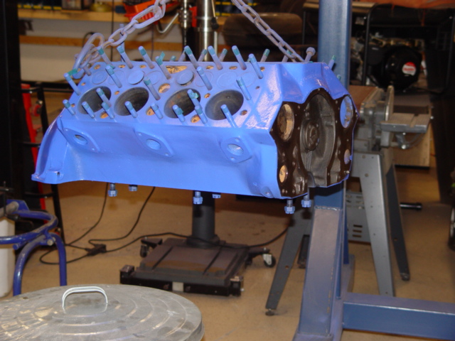
This is the
rear or the engine. You can easily see the half, Cast -in Bellhouseing that easily Identifies this Engine as a Pre-'49.
Together with the 59AB heads on our Engine, and the front mounted Distributor, we can safely assume our Engine is the 90/100HP
version produced between 1946-1948. Pictured is the Clutch, Pressure Plate, and Flywheel all mounted to the rear of
the Engine. Next we removed the pressure plate, with it's clutch and then the flywheel. The clutch was new and
there wasn't any marks on the pressure plate or flywheel, this clutch assembly was new or very recently replaced
before the engine had troubles. The rod bolts were next to be removed, and they were plenty tight but came right off.
I lightly sanded the top edge of the cylinder walls to remove the lip, then we slipped the pistons out of the good side of
the engine. They popped right out, with only a slight hang as they slid over the ridge at the top of the cylinders.
The bad side, or the side that had been left open to the elements for all these years was a little more involved. Two
(2) of the pistons came out relatively easy, but the other two (2) were ceased into the cylinder and required alot of force
to break them loose. I repeatedly oiled them and used a large hammer and block of old hard wood to loosen them.
They booth eventually loosened, but not till the old Flathead let me know those the boss. These also had a hard time
sliding over the ridge at the top of the cylinders, one of the lower rings broke on one of the pistons.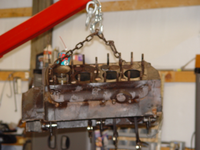
In this somewhat
bad picture, you can see the rods hanging out the bottom of the engine, and just how dirty the engine got while we were trying
to remove the pistons. As the parts were removed and the wear surfaces inspected, everything was in excellent shape. After
the pistons were out, we dropped the main caps and remover the crank-shaft. Again, all the wear surfaces were in very
good shape. I almost think this engine was freshened, just prior to it's over heating and eventual cracked
block between two (2) of the valves. The clutch, flywheel and pressure plate were all new. The inside of
the engine was in excellent condition, with perfect looking bearings, and on the closed side of the engine, we could see the
hone marks in the cylinders. It almost makes me think someone forgot or left something out, which caused the engine
to over heat and then crack the block. Just a theory, but it sure would explain alot of things. We kept all the
nuts, bolts, bearings and what-not in a container for latter-on when we re-assemble the engine. Al thought we have bought
new Stainless Steel hardware, it's till a good ideal to keep all the old parts till you are sure you no longer might need
them.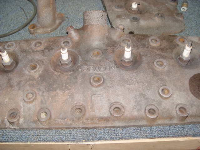
In this close-up
shoot of the Heads, you can read the 59 A-B designation of them. Right now we have the engine torn down and all the parts in one
group. We will start the restoration one part at a time.Oil Pan
The
Oil Pan was very dirty inside, it had years of sludge build-up and dirty oil that needed to be removed. We used some
mineral oil to cut through the dirt and sludge and in no time and the Pan cleaned up very nicely. The big dent
in the bottom of the Oil Pan was fairly easy to remove. Now with access to the inside, we simply finessed the dents
out one by one and restored the Oil Pan to it's original shape. We used several different hammers and some blocks
of hard wood to reach the inside and it's corners. The exterior of the Oil Pan was very pitted and rusted.
The rust was easy to remove using a wire wheel brush in our side grinder, and some sanding disc. But the pitting, was
not an easy fix. I sanded the pits down as much as I could, using some abrasive 4-1/2" disc in our side grinder.
But, the remaining pits would have to be smoothed out with body filler. I applied two coats of Rage Gold Body Filler
too the areas that were either pitted or damaged in such a way that we could not restore them. This stuff sets up very
quick in the heat, so you have to really be ready and apply it quickly. What with our 90°+ conditions, I had to
work very quickly to get the coverage I wanted. You can start sanding within 10-15 minuets, as it sets up very quickly.
I sanded the Pan down to a good smooth surface, latter when we are closer to Painting time, I will continue the sanding
till I have a very smooth and straight surface to work with. We also have to modify each side of our Oil pan. We need to install
some means of an Oil Drain on each side for the Turbo-Chargers Oiling System. The oil enters each Turbo-Charger through
a AN-4 Hose. This small line is all thats needed to supply the Turbo with clean, fresh, pressurized Oil to
lubricate and cool the center bearing. But the drain needs to be much larger, we will use a AN-10 drain line that will
go from the bottom of the Turbo-Charger to the fitting we need to install in the upper portion of the Oil Drain Pan.
The need for such a large line is the product of Oil Foaming, as the oil is sprayed on the center bearing to lubricate and
cool it, the shaft that the bearing supports is spinning very Fast. When I say Fast, I mean Very Fast. This shaft
is spinning up too 150,000 RP M's, and at that kind of speed, the Oil is supper aerated and foams, thus the need for a
large oil drain line. Our Project: Flathead will need some sort of Fitting installed in it's Oil Pan that will allow
our AN-10 Hose to connect with it. And it needs to be installed high enough that the Fitting is above the running Oil
level of the Oil Pan, otherwise it will not drain.08-15-07 
I
decided to go with a An-10 Fuel Cell Fitting, as the return Turbo-Charger Oil Fitting for the Oil Pan. We purchased
two (2) of them, one for each side, from Jeg's Mail Order. These will make for a fast, leak-proof connection and
can be installed anywhere we choose in the Oil Pan. There was Three (3) ways we could have gone about installing a Fitting
like this in the Oil Pan. 1.
Purchasing a Steel An-10 Adapter Fitting and welding it to the pan.2. Doing what most Turbo-Charging or Super-Charging kits do, and use a special made punch, that pouches
a hole in the oil pan in such a way that you can then tap the hole and screw in your fitting. This is OK, but mainly
made for the people that need the fitting, but can't or don't want to drop the pan to install it.3. Do as we did and drill a hole in the pan, and use the
An-10 fitting that seals itself. Of-coarse this method requires access to the inside of the pan. Not the type
problem Turbo-Charger Kit makers what their prospective customers to worry about.Crank-Shaft 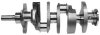
We will re-use the original stock Crank-Shaft. It is in great condition and has no none flaws.
The wear surfaces look extraordinary and the bearings are in excellent shape.Fly-Wheel
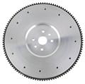
Our Fly-Wheel is also in excellent shape, In-fact I believe it along with the Pressure-Plate and Clutch, were
both new and or recently replaced. We will clean-up the Fly-Wheel and re-use it in Project:Flathead.Pressure Plate Our Press-Plate is in very good condition. I believe it was recently re-placed just before
the engine suffered it's debilitating cracks.Clutch Plate
The Clutch Plate is in very good condition, and I believe
it was recently replaced just before the engine had trouble.Block We will be re-using our stock Block. The first step after the tear-down
was to re-clean the Block. While we had no rust to deal with, there was certainly plenty of oil, and grime. I
positioned the Block on a rolling dolly, and pushed it outside. There we pressure washed it, and hand scrubbed the Block
with Hot soapy water. There were a few highly concentrated areas of grease and oil build-up that required the help of
some more Mineral oil. This area was basically restricted to the rear of the Bock were the Fly-Wheel is. This
build-up was the result of a leaking Rear Main Seal, and Clutch Dust. Next we will concentrated of the Block itself. I want to smooth-Up the Block
as much as possible. This entails the grinding and sanding down all the casting marks and rough edges all over the Blocks
outer surfaces. If you ever get the chance to see a Flathead Engine up close, you'll readily see what it is I'm
trying to rid. This section will take some time, and I'll per-sue it on a now and then type bases. What I
hope to achieve is a Smooth, better looking Block, that will look very sharp after it is painted.Cylinder Head Studs:
I am planing on re-using the cylinder head studs, if
this were to be a running engine, I would certainly exchange the stock studs with New ARP high strength studs. The additional
pressure the Twin-Turbo-Chargers will put on the engine and especially the head studs make that change a must. But were
going to re-use them, and to do so we need to resolve a few issues. The one side of the engine has had it's head
removed for more then 40 years. This has allowed the elements to attack not only the cylinder walls, but also the head
studs. The threads are a bit rusty and to fix that, we will chase each stud with a 7/16"-14 die. This isn't
as bad a job as it might seem, and really went very fast. I simply chucked up a 3/8" adapter in my battery drill
and attached a 1" socket. Then I used some Tap-Ease on each stud and hand started the die, then used my battery
drill to spin down the die, and then re-move it. Just take your time and make sure you correctly start each stud.
We did order new 11/16" (measured across the nut) head nuts, with new chrome acorn nut covers. This will give our
Flathead a great , snug fitting, head with plenty of good looks.Water Pumps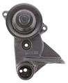
We will also be re-using our original Water Pumps.
One is in great working condition and looks like it was replaced at the time of the re-build. It has the newer pump
design and I think I read it's suppose to pump 40% better. The other pump has to be an original, It's pretty
rusted and has a very small impeller that almost has no set in it. To clean the Water Pumps, I will Glass Bead them
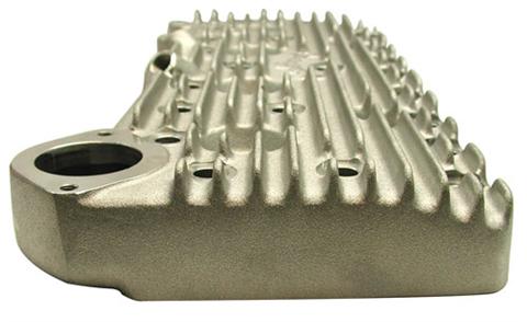
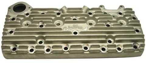
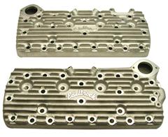
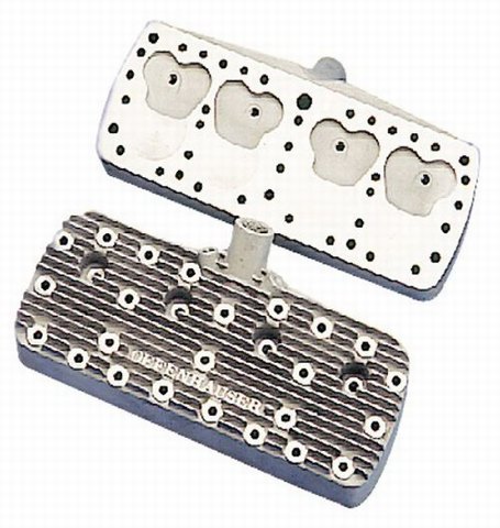
in our sand blasting cabinet, this will restore the surface, while not harming it as other mediums might.Cylinder Heads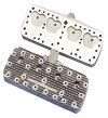 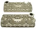
Pictured are
two (2) of the more popular replacements for the stock Cylinder heads on a Ford Flathead Engine. The fist is a Offenhauser
Finned Aluminum Head, and the second one, a Edelbrock Finned Aluminum Head. Both offer higher compression ratios, better
breathing and increased heat dissipation, all the more reason why these replacement Heads should be throughly checked out
if you are planning your own Flathead Rebuild. Our Cylinder heads will also be re-used. While I would love to purchase a set of Elderbrock
or Offenhauser Aluminum Finned Heads, I just don't see them in the budget at this time. Maybe down the road??
But who knows.
We will start by cleaning up our stock Cylinder heads in the sand blasting cabinet. Again I will use the Glass
Beads, so they clean but don't harm our Heads. Well we couldn't leave well enough alone, I broke down and bought new Elderbrock
Finned Aluminum Heads for Project: Flathead . The
original ones shown elsewhere in this section were not bad, and I would have considered them to be in excellent shape, just
this project has snow-balled into a more elaberate design then first stated. The racing heads from Edelbrock will finsh
out the overall theme and appearance of the project.
Ignition System  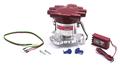 The above shows
some of the components that will be used in our Engine. The Distributor will be a new unit, and be fully electronic.
Our Project:Flathead came
with a points type Distributor that worked in the old days, but just wouldn't cut it with what we plain to do. By
pressurizing the Cylinders, we are making the Ignition System work hard to light the Fuel Mixture. We need a Ignition
System that will work at high RP M's and High Boost Levels, as well as it works with no Boost and at Idle. We will
use a New Electronic Distributor along with a new coil and Plug Wires.Items Needed to make the Ignition System Work 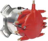
1. New MSD 8351 Distributor Pro-Billet Front Mount Flathead
Distributors
 Early Flathead racers and cruisers alike will be excited to see these new front mount Flathead
Distributors! These distributors are built around a CNC machined billet aluminum housing for precise tolerances. Early Flathead racers and cruisers alike will be excited to see these new front mount Flathead
Distributors! These distributors are built around a CNC machined billet aluminum housing for precise tolerances.
The distributor is topped off with MSD’s new Crab Cap with spark plug style terminals for improved wire connections.
Just under the cap and Rynite race rotor is MSD’s adjustable mechanical advance. This assembly features chrome moly
construction with TIG-welded weight pins to secure the precision fine blanked weights. MSD supplies different advance springs
and stop bushings so you can dial-in an advance curve to meet your Flathead’s specs.
Just under the advance is MSD’s race proven magnetic pickup. This pickup, combined with a reluctor, produces accurate
trigger signals that are responsible for firing the MSD Ignition Control. Bring your Flathead up-to-date with MSD performance.
NOTE: Must be used with an MSD 6, 7, 8 or
10 Series Ignition. |
| |
  2. New Red-Line Spark Plug Wires W/90° Ends-8
3.
MSD 6AL Multi-Strike Ignition Box
The MSD
6A is the base model of the capacitive discharge multiple spark 6 Series design. Whether you have a powerful
street machine, hard working truck or trick street rod, the powerful multiple sparks of the MSD 6A will ensure complete combustion. Benefits such as quicker ET’s, easier starting, reduced
plug fouling, more power and even increased fuel economy can be expected with the 6A’s high energy multiple sparks.
Like all of the MSD 6 Series Ignitions, the
6A will work with virtually any vehicle as long as it has a 12-18 volt electrical system. It can be triggered using breaker
points, a magnetic pickup or the output of an electronic amplifier. All necessary parts and wiring instructions are included.
MSD 6A, 4, 6, 8-Cylinder
PN 6200 MSD 6A, Odd-Fire
V6
PN 6246
OPERATING
SPECIFICATIONS | | Operating Voltage: | +10-18 VDC Negative Ground | | Current Requirements: | 5 Amps-5,000 RPM
10 Amps-10,000 RPM | | RPM Range: | 15,000 RPM with 14.4 Volts | | Spark
Duration: | 20°
Crankshaft Rotation | | Energy Output Max: | 105-115 mJ Per Spark | | Weight and Size: | 2.75 lbs, 8"Lx3.5"Wx2.25"H | | Voltage Output Max: | Primary: 460-480 Volts
Secondary:
45,000 Volts (Blaster Coil) |
| | | |
Since we went with the MSD Distributor, it only makes since to stay with that brand for
the remaining ignition system. Yes, you can mix and match the various coils, ignition boxes and so forth, and I have
done that in the past, but it's better to stay with the same brand. You get a system that was designed to
work with each piece, and maximum performance for each dollar spent.
4. Ignition Coil
MSD Blaster Coils
If you are
looking to upgrade your stock coil, or want to compliment the performance of your MSD Blaster Ignition, MSD 5, 6 or 7, the Blaster Coil line is the right choice.
All of the Blaster Coils are designed for improved spark output!
Special 100:1 windings are used to provide maximum build-up of voltage! These windings are held secure and kept cool in an
oil filled metal canister. The tower assembly is molded of durable alkyd material due to its high dielectric characteristics
while wide spaced brass primary terminals prevent the possibility of spark.
There are several versions of the Blaster Coil available. All of them have the same internal specifications, but have different
housings or components. Each Blaster Coil can be used with a stock ignition, Blaster Ignition, MSD 5, 6 or 7 Ignition Control.
Most late model vehicles with electronic ignitions do not require a ballast resistor, check your ignition and manufacturers
specifications to determine if a ballast is required in your application.
| BLASTER 2 AND
3 SPECIFICATIONS | | Output Voltage: | 45,000 Volts Maximum | | Operating
Voltage: | 12VDC | | Primary Resistance: | 0.7 Ohms | | Secondary
Resistance: | 4.7K Ohms | | Turns Ratio: | 100:1 |
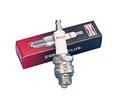
5. Spark Plugs
| | | |
While Spark Plugs might not be the toughest choice, they are a very real and important part of any Ignition System.
I found mainly Two (2) brands of Spark Plugs that were readily
available, Champion and Auto lite. Both quality Spark Plugs
and both a good choice. 6. Wire Looms
We will be using chrome tube type wire looms from Speedway Motors. They were by far the most competitive with reguards
to the looms and have always done a great job of getting me the parts I needed fast and accurate.
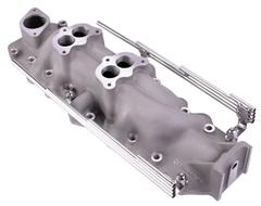
Intake Manifold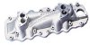 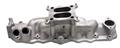 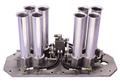 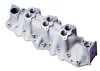 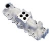 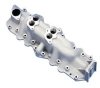 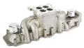
As
you can see, the Intake manifold is one part where their are plenty choices to be had. Starting from the top left and
going to the right, you have Elderbrock's Super Dual Intake, and their Single 4-Barrel intake, Hilborn's Fuel
Injection intake, Offenhauser's "Offy" Triple Intake, The "Offy" Single Intake, "Offy's"
Regular Dual intake, and Speedway's High rise 4-Barrel intake. There are still many more intakes on the market,
with several alone from Eddie Mayer. Right now the plan is to re-use the original Intake Manifold and simply adapt it to our needs.
  Update: Update:
This plan to re-use
the original Intake manifold was tossed into the fire, since then we have bought a new Speedway Motors Intake manidold.
I like this particular manifold for the large and meaty intake runners, which I hope to modify for the injectors. The
manifold is also set-up for a 4-barrle carburator, so it will be very easy to modify for out plentum/mass air set-up. Fuel Injection System We will be
using a Fuel Injection System that uses a Mass air Flow Sensor along with a Throttle Body and individual Fuel Injectors.
Our Fuel Injection System will be of the return type, and will need to use an Electric Fuel Pump, Fuel Regulator and a return
Fuel line.Items Needed To Make the Fuel Injection Engine Build-up
09-19-07
Today was an interesting day, we set out to do something I have never done
before......Powerder-Coat. I
bought the gun, power unit, powder and everything else needed to powder-coat several years ago, and just never used it, till
today. And the what was the first progect..?? Project:Flathead,
of-coarse. I had cleaned the block several times and it had even been sand-blasted several months ago, all in getting
ready for this day. The final clean was to wipe everything down with solvent and blow it dry. I have a small oven,
so the block wasn't going to fit in there, instead.. I planed to use 4-2000W heat lamps I have, each on there own roller
stand. I know this is a huge block of Iron to heat, and I had my doubts about weather this would work or not.
The color
I picked was Electric Blue, and I took a sifter to it before loading the powder into the container to be sure there wasn't
any lumps or pieces to large. That worked really well, just I need a larger funnel for the next batch. This stuff
is really fine, and has a liquid like fluidity. It will get every where!! The set-up is very simple, just plug in the power unit, attach
the ground wire and lay-out the foot-switch where it will be convenient to use while you are applying the powder. Then
just load the powder into the canister and attach the air line. I made up a regulator with gauge and a moisture filter,
so that they will plug into the application wand, this makes air adjustment simple and very convenient. You can simple
UN-plug the unit when you are finished and it stores very nicely. Air consumption is minimal, and you only need a few
pounds of air pressure.
In order to heat the block to the required 400°f temperature, I used a torch to pre-heat the block. If you had smaller
and lighter objects to coat, the heating lamps would work nicely, but the thick and solid engine block took some extra heat
to make everything work. All in all, I'm very pleased with the way it turned out, I gave it two (2) coats and the
coverage and color looks very good. I did not get the look I would have if I would have taken it to a professional powder-coater,
who had an oven large enough to hold the whole block. But, I also didn't have to pay the 250-300 dollars they would
have charged..... Don't get me wrong, I have spent plenty one the basic set-up and supplies, but stating with
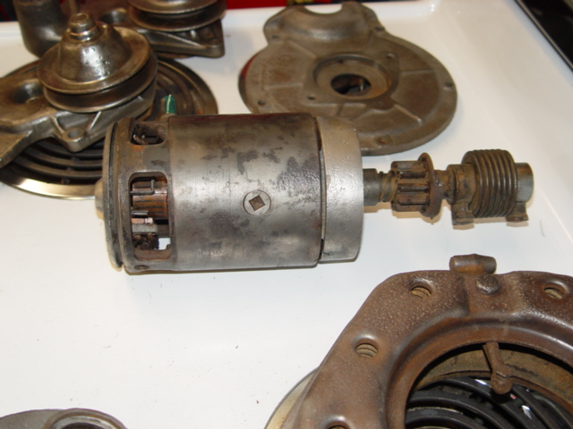
these block, those expenditures are starting to make a return. The rest of the day was spent cleaning the clutch pressure
plate, front cover, flywheel and starter for powder-coating tomorrow if everything goes as planed. I had to use booth
solvent and sand blasting on these pieces to get them into condition. These pieces will be small enough to fit in the
oven, so I'm expecting them to come out looking great, we'll see tomorrow. 09-20-07
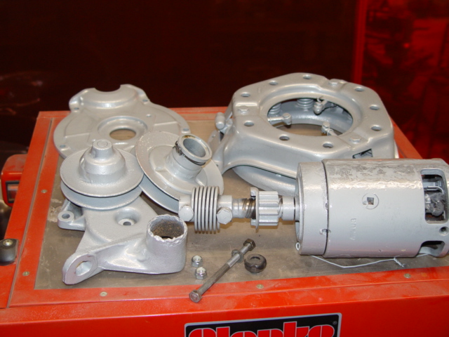
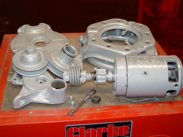
Well today we powder-coated parts for the very first time. It was a pretty good learning experiance, and I can tell
I got better with practice. I had some Mercedes Silver and used that on most of the parts, it's a nice medium type
silver. We also experimented a little with Clear, and Super Chrome. The flywheel got he Super Chrome, and the
Starter and Pulley got the Clear. It's really cool to see how things work and interact with each other. I
wouldn't call any of the parts we coated, professional looking, but they did turn out very nice for the first time use
of powder coating equipment and matterials. It's funny, when you are applying the powder it looks and feels like
your useing a bunch of powder, but all the parts, with some second coats only took a few ounces. 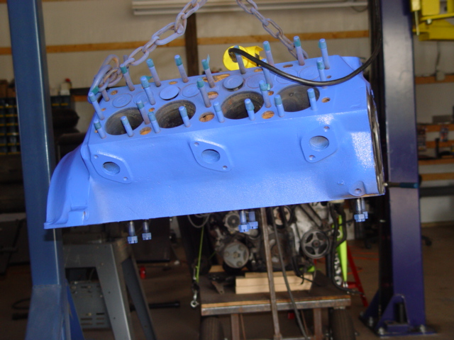
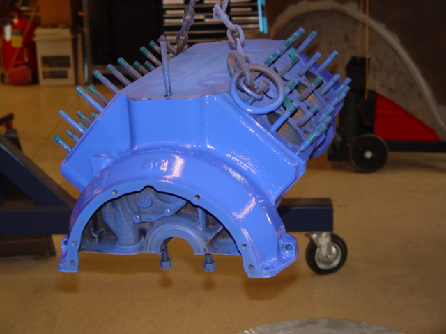
This is or Flat-head block after yesterdays Powder-coating exercise. It turned
out pretty good, but i could have used just a bit more heat. 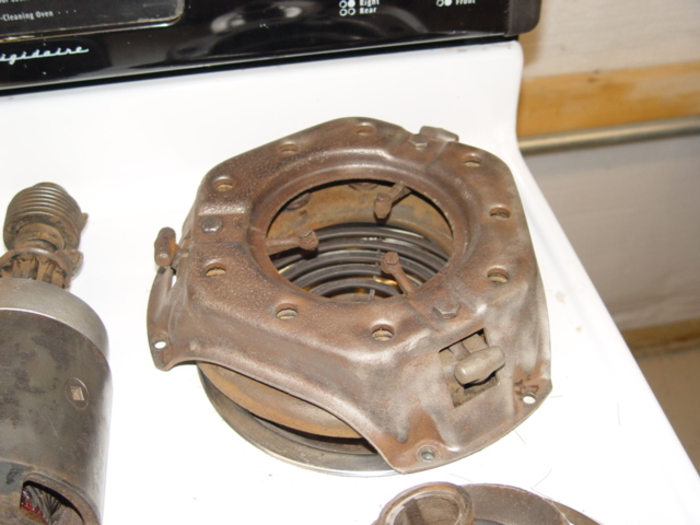
These are the parts we Powder-coated, or at least most of them. The flywheel
is not pictured. I'll
take some pictures of the finished product latter, next time I get to go down to the shop. I have to order some
gaskets and stuff for the Flathead, so we can keep moving forward. I suppose we are very close to starting the headers.
They will be fun, and I'm looking forward to building them. 09-21-07 Today we didn't work on Project:Flathead, but we did get alot of things done
for that project. As you may or may not remember, I had to do some body work on the oil pan because of some dents.
This ment I could now no longer powder-coat it, so it will have to be painted by more traditional means. One thing we
did today was to pick out the color and have the paint mixed. I wanted a smokey grey/silver with some metalic, and hopefully
the color I picked will reflect that. They didn't have a very organized color chart like say House Of Color has,
instead it was organized by year and make. That works fine for those in autobody, but not so fine for those tring to
find a perticular shade of color. I went to the local auto-parts wherehouser and they mixed the paint for me.
I also got some clear and some cleaning supplies to keep my spray gun in good working order. All told, $140.00 was the
damage, but that figure isn't really representable of what it cost to pain the oil pan. PARTS PLUS DITJC661-QT
HI-GLOSS MULTI-PANEL 15.85 DITJH6670-8OZ FAST HARDENER 12.85
DITJR506-GL
MEDIUM REDUCER 20.00 DITJH6002-8OZ ACRYLIC ENAMEL
21.00 D/BA44L
DURA-BLOCK SANDING KIT 50.49 TAX
7.93 140.12
Like I stated, this list
contains enough matterials to do several projects, so that price would have to be spread over all the projects to be fair.
I will say I was impressed with the guys down at the parts shop, they had me out the door in no time. This was the first
time I used this place, my regular paint store was sold and is now a fire place accessory store. The other thing I got done today was to find some long 5/16"
bolts to hold my starter together. The original screews were not there, so I hed to get them. I checked all the
Flathead parts stores, and know one sells them, they have the ones for the generators, but not the starters. I found
some 5/16" x 8" bolts at the local hardware store so I think they will do. One thing I forget to record, was the order I placed yesterday
for some Flathead parts. I ordered them from Mac's.
MAC's ANTIQUE AUTO PARTS 18-6020 FRONT TIMING COVER GASKET
0.95 40-6521
V-8 INTAKE MANIFOLD GASKET 4.90 48-6781 V-8 OIL PAN GASKET
9.75 52-6730
OIL PAN DRAIN PLUG
4.95 52-6734
DRAIN PLUG GASKET
1.05 48-6750
OIL PAN DIP STICK
8.95 48-6754-B
DIP STICK TUBE
6.25 A8115 BRASS
DRAIN COCK 2 @ 4.95 9.90
78-8507
WATER PUMP GASKETS 2 @ .55 1.10 SHIPPING 12.85
60.65
Today I also ordered what I hope will be the last parts for the Project:Flathead.
They all came from Speedway Motors, which I just so happen to think is the best mail order parts house out there. There
website is bar-none the best going, and they have great customer service and very , very competitive pricing. This one
order right here would have been more then $100.00 extra most other places.
SPEEDWAY MOTORS
91021003 Flathead Intake gasket
7.99 91015962 Speedway Intake Manifold 399.99
3251125
Edelbrock Finned Heads
499.99 91667908
Alternator bracket, plain
39.99 271H10
Champion Spark Plugs 8 @2.99 23.92 1353274 Ford frame adapters 24.99
91612001
SS Wire Looms
49.99 5478203
MSD Blaster Coil
44.99 5478203
MSD Coil Mount
5.99 shipping 41.02
$1,138.00 I also just remembered a Chrome Chevy Alternator I purchased from E-bay for 79.00.
I will use this with the alternator mount we just ordered from Speedway on the Flathead instead of the generator. Realisticly,
the generator isn't a good match for todays sensitive electronics, so converting it over to the alternator is a smart
move, besides it can put out 100A compared to the generators 30. 09-22-07
Man was it hot today, who would know it's the first day of Fall tomarrow?? Dispite the heat, we did get alot none
today. My Dad was working on installing the door skins on ProjectCOBRA'33,
so while he was grinding or sanding the door for proper fit, I worked on the Flathead. First up was getting the Oil
pan sanded and then painted. I had already applied the body filler and rough sanded it out. So that left me with
finish sanding, sand blasting some rust spots that grew since it was sand blasted way back when. I say it took me 2-2-1/2
hours to get the pan ready, it's not perfect by any means, but I don't want it perfect. It's an oil pan
from a 1946 Flathead, and I want it to look it's age, just cleaned up a bit. I really liked the paint I choose,
it was easy to work with and the application part was smooth. I foregot my camera, but I'll be sure to take it with
me next time and I'll get caught up on the picture taking side of things.....I promise. The starter was missing the mounting bolts and I tried to order
them from the mail order houses, but know one sold them.....so I made some. I took 2- 8-1/2" long 5/16"
carrage bolts and cut the end off both of them, then I welded a 3/8" stainless steel nut to each end. A little
time on the grinder and presto, 2 new 5/16" starter bolts. I kind of wished I would have waited on the powder-coating.
I really like the new color of the oil pan, and I would have liked to spray some of the other parts in the same color.
They would have looked much better, cause some of the powder-coated items clumped up alittle. The new color is super
glossy and I like the smoky metalic color. I got to looking at the engine block, and while the color looks nice, the finish
is slightly off. The areas where there was plenty of heat, mainly the ends, is noticably more glossy then the sides.
So...I decided to give it a coat of clear, and after roughtly 3 coats of clear it looks really nice. All the surfaces
are equal now and it brought the color out and made it a little more bright, I like it, and I think you will too. I
suppose thats it for now, we have the parts coming in latter this week, which will allow us to button-up the engine.
09-26-07
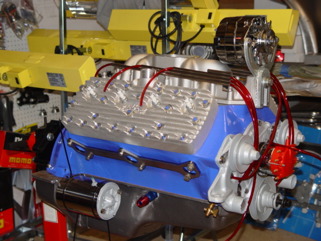
Wow, today turned out great! What started as a mild build-up has turned into a all out, bare no expense,
get out of our way we're going to the front of the class make over. The ideal today was to just set the engine on
the engine stand and maybe install a few parts, but that went out the door fast, and before I knew it the day was long gone
and we had a real good loking engine in front of us. This is how it went down. I was running a little behind today, so I didn't get to
the shop till 10:15. I started out by getting the engine off the lift and bolted to the engine stand. I am so
glade we clear coated the engine, it just made the color jump out at you. The differance is amazing and well worth the
expense and time it took. We got the engine loaded on the stand and wheeled it over to one of our benchs and started
by fliping it over and working on the bottom of the engine. We installed the bearings and greased them, them installed
the crank-shaft and then the main caps. Then the oil pan gasket and the front and rear crank-shaft seals. This
is somewhat confussing, and takes some time to get everything alined just right. The rear and front seal needs to be
rolled, so they expaind and fit into the carrier. The rear seal is the most time consumming, and probally the most important
interms of oil control. Just take your time and get everything in line and in-order. The pan goes on pretty easy,
with only a minimal amount of finessing needed. We used the stainless steel pan bolts from the kit we purchased way
back. Oh, let me back up a little. Before we installed the oil pan, I had to install two(2) oil return fittings,
we mentioned them earlier. Both were AN-10 fittings and had to be installed so they were above the normal oil level,
this way they would allow the oil to drain back from the turbo-chargers. On a Flathead engine, this isin't as easy
as you might thing. The oil pan is very close to all the crankshaft throws, and with the rods attached, the bolts are
very, very close to the pans insides. The only place that would work on a flatdead, is the area right were the middle
main bearing is located. This area is about 2" wide and the crank-shaft bearing throws are on each side of it,
so you have no interfearance. The only other consideration is the oil pan attachment bolt right in that area, try to
offset the fitting so the pan bolt can be installed. Our fitting has is a bolt-on type fitting witha internal and external
gasket. If you were to use a weld-in type fitting, you would have more options, as the portion that fits inside the
pan would be much smaller. As it would turn-out, the area we mounted our fitting works just fine for the oi pan and
the turbo-chargers we will be installing, your situation might be different, so compare the differances between the two (2)
styles of fittings.
Once the Oil-pan was installed we installed the starter, with those same bolts we fabricated the other day, and that went
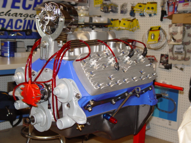
smoothly, the bolts worked great. Now we rolled the engine over and started on the top side. We installed the
two (2) water pumps and their gaskets, again we used the stainless steel bolts supplied in the kit we purchased. Then
the front cover and Mallery distributor, and the front was finished and looking good. Next we cut off all the tape we
applied to the head studs to protect the threads from the powder-coating, and installed the new Elderbrock heads and Speedway
Motros Inatke manifold. Now the engine was really looking right! First problem, the head studs along the bottom
edge of the block were not long enough. With the aluminum heads, we will need to install longer heads studs. It
would have been very convienent if someone would have told us about this problem. Or if say Elderbrock would have supplied
the longer head studs with there heads. None of the catalogs or web sites mention this little problem.....Why?
I have no problem, maybe they think you wont buy there heads if you learn you have to remove the head studs and replace them
with longer ones??? I installed the Wire looms and the spark plug wires to get a feel of what else will be needed.
The fuel injectors will interfeer with them as they were installed, so we'll have to find another way around this problem.
Also, I'm not to crasy about the RAJA plug ends, they seem very odd and don't offer one bit of insullation for the
plugs. I know they were used years ago, but this might be on of those items were we change to something more modern
and reliable. We'll tackle that problem latter, right now we are to the point were we will be starting the header
build. I installed the exhaust manifold flange, and it fit great, I just had to clean-out all the bolt holes with a
tap to remove the matterial that made it's way into the holes. The header is going to be a real chalenge, I'm
thinking about making them Equal Length headers which is an alltogether different animal then just plain headers, I'll
see how difficult it will be then make up my mine, right now I'm up for the challenge, and think it would be a cool new
ideal. 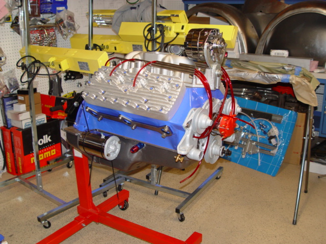
This just about wraps
up the flathead for this section. We did install the new brass block drains on each side. These came in in 1/8"
NPT, so I had to install 2-1/4" to 1/8" NPT bushings. I prefer this arangment, It makes future removeal easier,
as the brass on brass fittings don't usually seaze-up. The Oil feed for the turbo's was the same way.
We installed the same brass 1/4" to 1/8' NPT fittings then the AN-4-1/8" NPT aluminum fittings. This gives
us the two (2) An-4 oil feed lines we will need for the two (2) turbo-chargers we will be installing, and earilier we installed
the two (2) oil drain fittings in the oil pan they will both need. Oh, we also installed the chrome chevrolet alternator
and the new alternator bracket. This system looks pretty nice and it went on without problem, now all I need is the
proper belt to finish it off. The belt was ordered from Vintage Ford, along with some other small odds and ends we will
need. Order from
Sacramento Vintage Ford 5771-2 1942-1948 long belt
19.95 17115-B Color coded
plug wires 39.95
The rest of the order was a health supply of decals
and t-ee shirts, this company has a really nice selection of both.
Order
form Mac's Antique Auto Parts 48-6067 3.09" head studs 38-48' 24 ea
42.00 V8033125B Head stud Washers
48 ea 8.50 And a couple pictures of the 1933 Ford Tudor Sedan 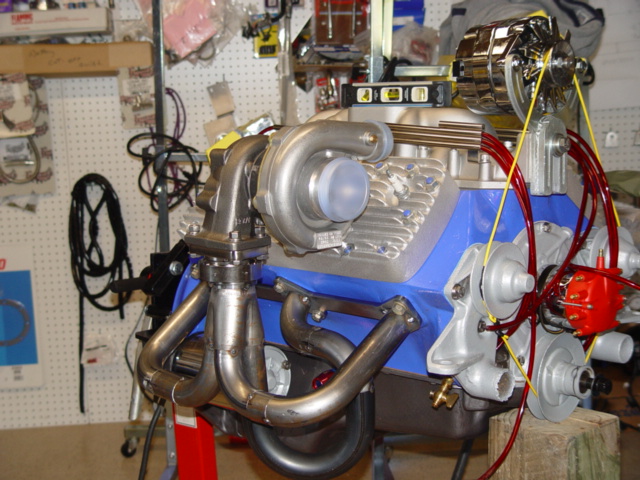 Just a little taste of what were doing over in section IV For more information of the Project:Flathead project see section IV, Putting it all Together.
|
|
|
Enter content here
|
|
|
Enter content here
|
|
|
Enter content here
|
|
|
Enter supporting content here
Pro Weld
5937 Ethan Drive
Burlington, KY 41005
859-586-4069
Proweld@myway.com
|
|
|
|