|
Welcome to the '09 Season!!
05-11-09
Wow ! Has it really been this long?....No
I haven't lost interest or gone bankrupt, but I have had an awful lot of health problems and rotten luck that has kept
me both physically and mentally away from the car I love. My son just ended his last semester of his third
year of school, he is learning to become a Mechanical Engineer, and a damn fine one at that. This is only
important because it is with his help and enthusiasm that I began work once again on Project COBRA'33. Where do we start?.. The car itself hasn't
been touched since our last post, some 8-9 months ago. The frame has been tucked upon a 4-post lift and
the body bolted to the body cart. I did start on the system to lift the car without damaging the frame
or paint, before we left off. I have all the main pieces to install the rear system, so it's just a
matter of finding the pieces and getting going. I decided to forgo any such system for the front frame
rails. I decided that whatever I fashioned, something close to the rear pieces, would eventually have to
rest so low to the ground that it would not be worth the effort. The new pieces would have to set under
the front frame rails, and there is just not enough room to do so safely. Instead, I'm just going to
bite the bullet and install small pieces of diamond patterned rubber pieces to protect and cover the frame area where the
lift arms will contact them. Yes, it will damage the frame in this area, and yes, I will just continue
to exchange the rubber matting as it gets abused. It's a car, and things have to be sacrificed for
service and normal wear items and maintenance. If I get to restore another car, or for your interest, I
would as I'm building the frame section, plan ahead and incorporate a lift point into the frame's overall design.
One that would bear the weight of the vehicle and one that would allow servicing without mar or destruction. First off, we had to get in the shop and
clean everything back up the way I like it to be. This meant pulling things up and sweeping the floors,
dusting off equipment and in general getting the place back in line. Because the car or at least it's
frame section is up on the 4-post lift, we need to get the floor area in and around the lift very clean. I
have to move many pieces of equipment to make room for the 4-post lift to be pulled out of the corner and into the main section
of the shop, this way we can angle the lift so the frame can be removed from the lift and placed on the shop floor.
The 4-poster works very well, and it came with huge casters, but because of the weight we are dealing with, an small
piece of metal or other Debra, will make moving the lift out a chore. I noticed that the last time we went
through this little game, we missed some metal shavings around the saw area. These shavings were picked-up
by the temporary tires we have on the frame, and it makes rolling them a task, one that will shred your hands if you are not
using quality gloves. Not a huge oversight, but one I hope not to repeat! My son and I had used the shop several times during
the winter and spring. We installed some mild performance parts on his Subaru
WRX and when spring came we did our usual coarse of maintenance on all the cars, plus I installed a completely new
set of high performance brakes, pads, rotors, hoses and shoes for my Subaru Outback.
The shops condition was as much out fault as anyone's, so now is the time to focused and clean. My
Dad did manage to get the shop sink installed and pre-piped for the hot water heater, which may or may not come latter, we
will see. It would be a nice feature! I suppose we spent about two hours each getting
the shop back up to standards, it's amazing how much we can leave lying around and not put up properly. I
do need to empty the oil container, it's about to burst it is so full. I haven't the foggiest how
I'll do that, last time I bleed off a few gallons at a time, but this time I am full (30 Gallons) and need a place to
dispose of it. One idea is to get several (6) 5-gallon buckets W/lids and empty the container that way,
when take the buckets to a disposal place. Then store the buckets for the next time. Sounds
like the most logical choice. Then once empty I can tackle a small but pesky drip that developed on a bottom
connection. Let's get that frame down off the lift!
First things first….I had remembered that I needed to get a temporary 5/8" x 6" set of bolts for the
lower shock mounts. Because of the way it worked out, the nice polished SS bolts we purchased in a kit
didn't fit, they were short by about an 1-1/2". With longer bolts in hand, we set out to mount
the new rear lift platforms and get the lower shock mounts bolted down. I really expected
this whole ordeal to take 30-40 minutes, but because of several un-foreseen problems, it turned into a three hour ordeal.
What went wrong? First there was a certain amount of memory problems, not a huge deal but enough
to cost some time. Then the we had to move the frame over about five-six inches on the lift, the rear tire
was very close to the edge, and we were afraid that when we lifted the opposite side up, the tire might slip off the lift.
Next we really had a lot of problems with the first (Drivers side) shock we went to remove. The
shock was barely adjusted to an kind of resistance with regard to the spring pressure, but in just that short time the aluminum
to aluminum contact between the shock body and adjusting ring, caused the two piece to bind-up. We had
to take the shock off without removing the pressure from the spring, so that cost us plenty of time.
Once the shock was off, I locked the lower mount in a vise and with the spanner wrench and plenty of lubrication and
force, we finally got the locking (adjusting) ring off. Once off, you could see where the two surfaces
had their problems and just where the galling occurred. My fix at the time, was to thoroughly clean the
threads on both pieces and apply a liberal coat of anti-size compound, I am hopeful this works. Since the
driver's side had been such a pain to remove, I went ahead and removed the passenger side shock and cleaned and anti-sized
the threads there as well, even though that side seemed fine. I had always intended to apply some type
of anti-size, but was more in line with applying it towards the end of the project, before the real tension was applied to
the shock springs? I guess you can learn from my problems and do it right from the very start.
Now that the rear shocks were both in-order, we could very easily add the new lift points in the rear that allow us
to pick-up the rear most portion of the frame (car) and not damage anything. The lift points simply install
under the rear axle tube, and attach to the lower 4-Bar arm mount and in the rear to the shock mount. The
attachment is clean and simple, but very strong with the mount being constructed of plate steel and the actual lift point
being a slice of 1-1/4" thick by 8" diameter aluminum bar stock. I used four - 3/8" x 2"
carriage bolts to attach each aluminum slice, this gives a very nice and easy to access, round lift point. While
the rear shocks and related materials are only temporarily attached, they are secure and capable of supporting the weight
of the frame. Really the only temporary feature, is now that I have everything mounted and complete, I
can go ahead and order the right size and length rear suspension bolts in polished stainless steel, so they complete the look
and feel of the construction. Because there is always so many variables with a project like this, I find
it much cheaper to simple use cheap, common grade bolts for the set-up, then once the right lengths and diameters are determined,
then go and order the right pieces in the correct finishes. While it might not look like it, there will
be well over one hundred dollars in polished stainless bolts to connect the various pieces be described above.
The lower 4-bar bolts had to be replaced because the lift points we made, used this location to attach to.
The bracket simply slips over the lower 4-bar and it's mounting point, meaning we now need mounting bolts another
1-1/2 longer, one for each side. The lower shock mounts never did work, even thought we purchased the two
kits that were supposed to be for or mounting type, they were a good inch or two too short. Because the
rear/lower shock mounts have to be spaced out from the axle tube, this keeps the coil spring from contacting the axle tube,
We were able to re-use the nice aluminum spacer that was a part of the kit. With the aluminum spacer, the
rear lift point bracket and the width of the shock itself, we needed 5/8" x 6" lower shock bolts, not the 4-1/2"
long ones in the kit. I do like the look of the socket head bolts that came in the kit, so when looking
for the replacements, I will try to find a SS socket head 5/8" x 6" fine thread bolts. Upstairs,
for the top shock mounts, I'm still out to lunch. Our set-up requires a spacer there too, roughly 1-3/4
to 2". While shopping for the bottom bolts, I'll try to find the same type bolt for the top, but
also some sort of decent looking spacer, because of its design I need the same 5/8" x 6" bolt for the top as I do
for the bottom. These bolts will go on my final hardware list, and once we have the body on frame, and
everything fitting body wise, I'll set out and order what's needed in.
Moving the frame….I will say this, the frame came off the lift much easier and nicer then it went on.
Really we just knew what we had to do, this time around…experience always makes a difference. With
the frame lowered, we angled the 4-post lift till it would clear the welding table and roll off the lift with-out a problem.
Then we just attached the lift ramps, removed the front casters and let the lift down, it gets low enough that there
really isn't much of an angle to the loading ramps, and that’s great for a low slung frame like we have.
Really the frame rolled off the lift with no trouble, once off we installed the caster plates, these are the rollers
that sit under the tires and allow you to easily roll the frame around, and got it into position between the 2-post lift.
This is where we called it a day, that is once the garage was back into shape and everything re-arranged.
My goal is to re-work the frame lift we made. if you remember, we made a frame lift that had a front
and rear section, I painted it yellow and it had arms that would span the distance of the front frame section and the rear
differential. The only problems we had, was I made the rear section for a typical car, and ours ended up
having so clearance issues because of the lower 4-bar mounts. I would have to re-make the rear support
arms if we used it at this stage of the build. What makes me think it would be worth the trouble, is it
puts the frame up much higher than the tire rollers, and makes fitting the fenders and any under car work much easier.
I like the ideal of sitting on the small roller seats and being even with the work. I suppose I
could alter the supports to lift from the new lift points we just installed, which would be great. I am
thinking where will be a lot of work to do at this stage, we have to fit all the fenders, the front needs the inner fenders
fitted first, then the radiator and it's supports. I have to order our hood, which will be custom made,
but before the order goes in and the metal starts lying, we have to have the car completely mocked- up like it will be in
the end. Next, the system that seems to plague me the most, the steering will have to be taken care of.
I am almost certain the steering column I have with all the parts will be useless, and I will have to resort to using
a Steer-Clear and new Shorty column. These are all just a part of what's to come…..so stay with
us and watch as Project COBRA'33 comes to its close.
05-25-09
Happy Memorial Day !!!! Take the time to think about what it stands for, and thank a Vet….
We've been busy around the Pro Weld place, and that includes working on Project Cobra'33. This
year I have the pleasure of working alongside my son, Chris. He's a great person and a very big help
in the shop, he's in his last year of college and will be majoring in Mechanical Engineering next year. I
am very proud of him and the way he handles himself. As you know, we cleaned-up the shop and managed to
get the frame back off the 4-post lift. Since then we have been busy building two new projects, that will
help the forward progress of Project COBRA'33. First project was to alter the frame holder/roller.
when I first built this piece, some two years ago, we built it to be adjustable and to conform to most situations.
Un-fortunately, those configurations didn't lend themselves to the unusual, Winters Quick-change rear end with
a 4-bar rear suspension. Because of that and the way the exhaust system and lift plates mount, there was
no way to mount the frame to the frame cart, or to effectively mount the frame to the cart. The only way
around this dilemma, was to modify the cart and add some new lift brackets, ones that are specific to this frame, but will
allow some modification, for other similar frames in the future. I decided to make the new brackets out
of 2" square tubing like the rest of the brackets, and have them insert into 2-1/2" tubing. Because
we already had brackets that were fitted to the 3" axle tubes, I made sure the new brackets would allow us to re-use
the special rear end tube brackets we already had. We simply had to make some new brackets and inner-brackets
that would allow us to clear the obstacles of our frame and still plug into the original frame cart. Once
the frame was lifted to make measurements of the rear end easy, we got to work cutting and welding together the pieces of
2 & 2-1/2" square tubing, that will make-up t the new brackets. As we stated, I built into these
brackets, a certain amount of adjustability, of both height and with adjustments, so they would work not only on our present
frame but hopefully on any feature frames. The finished product, was a highly adjustable set of brackets,
that re-used the original rear end brackets, and allowed us to get our frame up high enough to conveniently work on the fenders,
steering and other pieces, yet be sturdily held and safe to work in, around and under-Neath. In
all it took us something like 4 hours or so to build, with the most time consuming part being the many, many holes we had
to drill into the steel tubing to get the adjustability factor. Chris, had the pleasure of being the drill
press operator for the day, and drill well over 100 holes! We haven't had the time to finish painting
the pieces, but we did get the parts on and the frame up and secured to the newly modified frame cart. This
was important, because this will allow us to work more efficiently and safer on the frame. by having this
new frame cart, we will be able to easily fit the remaining body work and the more important, steering system.
As it is now, we have the frame roughly 24" up off the shop floor (floor to bottom of frame), this is ideal for
what we have to do. not to mention, the ability to also easily move the frame form place to place, safely
and easily! One down now just one more to go!!!
Project Two….Ok the frame is up in the air and now
easy to work on…let's get to the last obstacle. For some time we have been fighting the Body
every time we had to mount it to the frame for fitting reasons. Up till now, we have been using a very
crude and un-professional method of lifting the body up and down. We have been using the 2-post lift, with
a couple of large boards run through the window openings, and shimmed up with lumber pieces. OK, it worked
when we needed it, but it was far from right, and this isn't the way to proceed. Especially with the
prospect of mounting a fully painted body…..We need a better way. Being that we would eventually
have to build something to mount the finished body when that time comes, why not just go ahead and build that lift now?
This will allow us to mount the body a couple of dozen times it will take for this section of the build, with ease
and illuminate much frustration and prospect of possible body damage. So, the plan is to go ahead and build
the body lift now and do it right and get it over with! But, instead of just building a onetime body lift
that only fits this body style, we're going to take the time and build a very nice body lift that has plenty of adjustment
built in so we can re-use it many times in the future. Ok, the body lift will be constructed out of 1" and 1-1/2"
square tubing, in both 1/8" and 3/32" wall thickness. The lift will be built around the use of
the 2-post lift, I want the body lift to bolt to the lift arms in place of the adjustable lifting points. To
start with, we will remove the lift points, and make some pieces that fit snuggly to the arms of our 2-poster.
Here I cut 4- pieces of 4" x 4" x1/4" plate, then drilled the center of each plate with one 7/8"
hole. Then we used a 7/8" (which had no head)bolt and welded it to the center of the plate and allowed
it to protrude through the plate by some 3/8", this gave us a great amount to weld to. Now around
the stud, we cut 4-7/8" ID x 1-1/8" OD x 2-1/2" long sections of tubing, and welded them to the other side
of the plate and around the stud. This allows us to fill the 2-post lift arms tightly and still allow us
to secure a nut and washer to the underside of the lift arm, thus retaining the body lift tightly and securely to the 2-post
arms. Now on the up side of these plates, we welded a 9" long section of 1-1/2"
square tubing, which will be the receptacle for the rest of the body lift to attach to. Since we are using
1" and 1-1/2" sq tubing, we use the 1-1/2" tubing with holes drilled into the sides and
nuts welded to the tubing, so we can screw in 3/8" bolts which are used to hold the 1" tubing which slides inside
the 1-1/2" piece, it's a pressure fit and works very well. Simply insert the smaller tubing into
the 1-1/2' tubing pieces, and tighten down the 3/8' bolts. I've used this method many times
before for similar projects and it works extremely well. With all 4 corners now finished we have a great
platform to build upon. Now we roll in the body and take a few measurements, I want the lift to utilize
the front and rear windows as the lift points, but to make the lift re-usable for other projects we will make the rear window
opening the same location as the rear most lift post, and then make the front lift post adjustable, for longer bodies.
We need to build 4-upper lift corners, these will have a 90° section that angles in toward the inside of the body,
and another 90° corner, but this one angling forward towards the other (front) post. The two rear pieces
that angle in towards the interior of the body, will be joined together by a single piece of 1" steel tubing, which will
simply slide inside the sections, and then we will hold them in place with 2-per side, 3/8" bolts. This
will be the section that lifts the rear of the body. The system is repeated for the front of the body as
well, the section that simply angle toward each other, will also be connected by 1" tubing, but these are to keep the
spacing and help support the 4-lift post. Where the 2-rear lift post are also the extreme rear most of
the body lift, the front lift post are somewhat much more forward, and will allow for longer bodies. Here
we will use a sliding front lift post, which will be supported by a similar interconnecting side bar, but this one connects
the bottom of the post together. This is the basic frame structure that will comprise the body
lift. The bars the span the inside of the body, running from side to side, will also have adjustable lift
points. These pieces have 8" long x 1-1/2" wide sections for flat stock welded onto a small 5'
long piece of 1/1/2" tubing, this allows the supports to slide in and out, so they can be aligned with the window opening,
allowing the flat stock to spread the lifting forces out over a wider area, illuminating body damage from using the lift.
later when we lift the finished body, these pieces will be covered with protective wrap to protect the body from scratches
or other damage. In all there were 4- top corner brackets, 4-bottom lift arm brackets, 4-sliding lift point
brackets, 2-front sliding front post brackets and 2-front lift post/side support brackets that make up our body lift.
The objective was to make a safe and easy to use body lift, that could be used for future projects and be broken down
for storage. What we ended up with is exactly that, we have a great body lift that will safely lift both
our working and finished body on and off the frame, but will come apart and store with minimal room once finished.
In all it took some 6.5 hours for two people to finish, and burned up some 75-3/8bolts, 75-spring nuts, 40' of
1" tubing and 20' of 1-1/2" tubing. Eventually we will paint all the brackets and hopefully
have some nice photos to show.
05-25-09
Happy Memorial Day !!!! Take the time
to think about what it stands for, and thank a Vet….
We've been busy around the Pro Weld place, and that
includes working on Project Cobra'33. This year I have the pleasure of working alongside my son, Chris.
He's a great person and a very big help in the shop, he's in his last year of college and will be majoring
in Mechanical Engineering next year. I am very proud of him and the way he handles himself.
As you know, we cleaned-up the shop and managed to get the frame back off the 4-post lift. Since
then we have been busy building two new projects, that will help the forward progress of Project COBRA'33.
First project was to alter the frame holder/roller. when I first built this piece, some two years
ago, we built it to be adjustable and to conform to most situations. Un-fortunately, those configurations
didn't lend themselves to the unusual, Winters Quick-change rear end with a 4-bar rear suspension. Because
of that and the way the exhaust system and lift plates mount, there was no way to mount the frame to the frame cart, or to
effectively mount the frame to the cart. The only way around this dilemma, was to modify the cart and add
some new lift brackets, ones that are specific to this frame, but will allow some modification, for other similar frames in
the future. I decided to make the new brackets out of 2" square tubing like the rest of the brackets,
and have them insert into 2-1/2" tubing. Because we already had brackets that were fitted to the 3"
axle tubes, I made sure the new brackets would allow us to re-use the special rear end tube brackets we already had.
We simply had to make some new brackets and inner-brackets that would allow us to clear the obstacles of our frame
and still plug into the original frame cart. Once the frame was lifted to make measurements of the rear
end easy, we got to work cutting and welding together the pieces of 2 & 2-1/2" square tubing, that will make-up t
the new brackets. As we stated, I built into these brackets, a certain amount of adjustability, of both
height and with adjustments, so they would work not only on our present frame but hopefully on any feature frames.
The finished product, was a highly adjustable set of brackets, that re-used the original rear end brackets, and allowed
us to get our frame up high enough to conveniently work on the fenders, steering and other pieces, yet be sturdily held and
safe to work in, around and under-Neath. In all it took us something like 4 hours or
so to build, with the most time consuming part being the many, many holes we had to drill into the steel tubing to get the
adjustability factor. Chris, had the pleasure of being the drill press operator for the day, and drill
well over 100 holes! We haven't had the time to finish painting the pieces, but we did get the parts
on and the frame up and secured to the newly modified frame cart. This was important, because this will
allow us to work more efficiently and safer on the frame. by having this new frame cart, we will be able
to easily fit the remaining body work and the more important, steering system. As it is now, we have the
frame roughly 24" up off the shop floor (floor to bottom of frame), this is ideal for what we have to do.
not to mention, the ability to also easily move the frame form place to place, safely and easily! One
down now just one more to go!!!
Project Two….Ok the frame is up in the air and now
easy to work on…let's get to the last obstacle. For some time we have been fighting the Body
every time we had to mount it to the frame for fitting reasons. Up till now, we have been using a very
crude and un-professional method of lifting the body up and down. We have been using the 2-post lift, with
a couple of large boards run through the window openings, and shimmed up with lumber pieces. OK, it worked
when we needed it, but it was far from right, and this isn't the way to proceed. Especially with the
prospect of mounting a fully painted body…..We need a better way. Being that we would eventually
have to build something to mount the finished body when that time comes, why not just go ahead and build that lift now?
This will allow us to mount the body a couple of dozen times it will take for this section of the build, with ease
and illuminate much frustration and prospect of possible body damage. So, the plan is to go ahead and build
the body lift now and do it right and get it over with! But, instead of just building a onetime body lift
that only fits this body style, we're going to take the time and build a very nice body lift that has plenty of adjustment
built in so we can re-use it many times in the future. Ok, the body lift will be constructed out of 1" and 1-1/2"
square tubing, in both 1/8" and 3/32" wall thickness. The lift will be built around the use of
the 2-post lift, I want the body lift to bolt to the lift arms in place of the adjustable lifting points. To
start with, we will remove the lift points, and make some pieces that fit snuggly to the arms of our 2-poster.
Here I cut 4- pieces of 4" x 4" x1/4" plate, then drilled the center of each plate with one 7/8"
hole. Then we used a 7/8" (which had no head)bolt and welded it to the center of the plate and allowed
it to protrude through the plate by some 3/8", this gave us a great amount to weld to. Now around
the stud, we cut 4-7/8" ID x 1-1/8" OD x 2-1/2" long sections of tubing, and welded them to the other side
of the plate and around the stud. This allows us to fill the 2-post lift arms tightly and still allow us
to secure a nut and washer to the underside of the lift arm, thus retaining the body lift tightly and securely to the 2-post
arms. Now on the up side of these plates, we welded a 9" long section of 1-1/2"
square tubing, which will be the receptacle for the rest of the body lift to attach to. Since we are using
1" and 1-1/2" sq tubing, we use the 1-1/2" tubing with holes drilled into the sides and
nuts welded to the tubing, so we can screw in 3/8" bolts which are used to hold the 1" tubing which slides inside
the 1-1/2" piece, it's a pressure fit and works very well. Simply insert the smaller tubing into
the 1-1/2' tubing pieces, and tighten down the 3/8' bolts. I've used this method many times
before for similar projects and it works extremely well. With all 4 corners now finished we have a great
platform to build upon. Now we roll in the body and take a few measurements, I want the lift to utilize
the front and rear windows as the lift points, but to make the lift re-usable for other projects we will make the rear window
opening the same location as the rear most lift post, and then make the front lift post adjustable, for longer bodies.
We need to build 4-upper lift corners, these will have a 90° section that angles in toward the inside of the body,
and another 90° corner, but this one angling forward towards the other (front) post. The two rear pieces
that angle in towards the interior of the body, will be joined together by a single piece of 1" steel tubing, which will
simply slide inside the sections, and then we will hold them in place with 2-per side, 3/8" bolts. This
will be the section that lifts the rear of the body. The system is repeated for the front of the body as
well, the section that simply angle toward each other, will also be connected by 1" tubing, but these are to keep the
spacing and help support the 4-lift post. Where the 2-rear lift post are also the extreme rear most of
the body lift, the front lift post are somewhat much more forward, and will allow for longer bodies. Here
we will use a sliding front lift post, which will be supported by a similar interconnecting side bar, but this one connects
the bottom of the post together. This is the basic frame structure that will comprise the body
lift. The bars the span the inside of the body, running from side to side, will also have adjustable lift
points. These pieces have 8" long x 1-1/2" wide sections for flat stock welded onto a small 5'
long piece of 1/1/2" tubing, this allows the supports to slide in and out, so they can be aligned with the window opening,
allowing the flat stock to spread the lifting forces out over a wider area, illuminating body damage from using the lift.
later when we lift the finished body, these pieces will be covered with protective wrap to protect the body from scratches
or other damage. In all there were 4- top corner brackets, 4-bottom lift arm brackets, 4-sliding lift point
brackets, 2-front sliding front post brackets and 2-front lift post/side support brackets that make up our body lift.
The objective was to make a safe and easy to use body lift, that could be used for future projects and be broken down
for storage. What we ended up with is exactly that, we have a great body lift that will safely lift both
our working and finished body on and off the frame, but will come apart and store with minimal room once finished.
In all it took some 6.5 hours for two people to finish, and burned up some 75-3/8bolts, 75-spring nuts, 40' of
1" tubing and 20' of 1-1/2" tubing. Eventually we will paint all the brackets and hopefully
have some nice photos to show.
05-25-09
Happy memorial Day !!!! Take the time
to think about what it stands for, and thank a Vet….
We've been busy around the Pro Weld place, and that
includes working on Project Cobra'33. This year I have the pleasure of working alongside my son, Chris.
He's a great person and a very big help in the shop, he's in his last year of college and will be majoring
in Mechanical Engineering next year. I am very proud of him and the way he handles himself.
As you know, we cleaned-up the shop and managed to get the frame back off the 4-post lift. Since
then we have been busy building two new projects, that will help the forward progress of Project COBRA'33.
First project was to alter the frame holder/roller. when I first built this piece, some two years
ago, we built it to be adjustable and to conform to most situations. Un-fortunately, those configurations
didn't lend themselves to the unusual, Winters Quick-change rear end with a 4-bar rear suspension. Because
of that and the way the exhaust system and lift plates mount, there was no way to mount the frame to the frame cart, or to
effectively mount the frame to the cart. The only way around this dilemma, was to modify the cart and add
some new lift brackets, ones that are specific to this frame, but will allow some modification, for other similar frames in
the future. I decided to make the new brackets out of 2" square tubing like the rest of the brackets,
and have them insert into 2-1/2" tubing. Because we already had brackets that were fitted to the 3"
axle tubes, I made sure the new brackets would allow us to re-use the special rear end tube brackets we already had.
We simply had to make some new brackets and inner-brackets that would allow us to clear the obstacles of our frame
and still plug into the original frame cart. Once the frame was lifted to make measurements of the rear
end easy, we got to work cutting and welding together the pieces of 2 & 2-1/2" square tubing, that will make-up t
the new brackets. As we stated, I built into these brackets, a certain amount of adjustability, of both
height and with adjustments, so they would work not only on our present frame but hopefully on any feature frames.
The finished product, was a highly adjustable set of brackets, that re-used the original rear end brackets, and allowed
us to get our frame up high enough to conveniently work on the fenders, steering and other pieces, yet be sturdily held and
safe to work in, around and under-Neath. In all it took us something like 4 hours or
so to build, with the most time consuming part being the many, many holes we had to drill into the steel tubing to get the
adjustability factor. Chris, had the pleasure of being the drill press operator for the day, and drill
well over 100 holes! We haven't had the time to finish painting the pieces, but we did get the parts
on and the frame up and secured to the newly modified frame cart. This was important, because this will
allow us to work more efficiently and safer on the frame. by having this new frame cart, we will be able
to easily fit the remaining body work and the more important, steering system. As it is now, we have the
frame roughly 24" up off the shop floor (floor to bottom of frame), this is ideal for what we have to do.
not to mention, the ability to also easily move the frame form place to place, safely and easily! One
down now just one more to go!!!
Project Two….Ok the frame is up in the air and now
easy to work on…let's get to the last obstacle. For some time we have been fighting the Body
every time we had to mount it to the frame for fitting reasons. Up till now, we have been using a very
crude and un-professional method of lifting the body up and down. We have been using the 2-post lift, with
a couple of large boards run through the window openings, and shimmed up with lumber pieces. OK, it worked
when we needed it, but it was far from right, and this isn't the way to proceed. Especially with the
prospect of mounting a fully painted body…..We need a better way. Being that we would eventually
have to build something to mount the finished body when that time comes, why not just go ahead and build that lift now?
This will allow us to mount the body a couple of dozen times it will take for this section of the build, with ease
and illuminate much frustration and prospect of possible body damage. So, the plan is to go ahead and build
the body lift now and do it right and get it over with! But, instead of just building a onetime body lift
that only fits this body style, we're going to take the time and build a very nice body lift that has plenty of adjustment
built in so we can re-use it many times in the future. Ok, the body lift will be constructed out of 1" and 1-1/2"
square tubing, in both 1/8" and 3/32" wall thickness. The lift will be built around the use of
the 2-post lift, I want the body lift to bolt to the lift arms in place of the adjustable lifting points. To
start with, we will remove the lift points, and make some pieces that fit snuggly to the arms of our 2-poster.
Here I cut 4- pieces of 4" x 4" x1/4" plate, then drilled the center of each plate with one 7/8"
hole. Then we used a 7/8" (which had no head)bolt and welded it to the center of the plate and allowed
it to protrude through the plate by some 3/8", this gave us a great amount to weld to. Now around
the stud, we cut 4-7/8" ID x 1-1/8" OD x 2-1/2" long sections of tubing, and welded them to the other side
of the plate and around the stud. This allows us to fill the 2-post lift arms tightly and still allow us
to secure a nut and washer to the underside of the lift arm, thus retaining the body lift tightly and securely to the 2-post
arms. Now on the up side of these plates, we welded a 9" long section of 1-1/2"
square tubing, which will be the receptacle for the rest of the body lift to attach to. Since we are using
1" and 1-1/2" sq tubing, we use the 1-1/2" tubing with holes drilled into the sides and
nuts welded to the tubing, so we can screw in 3/8" bolts which are used to hold the 1" tubing which slides inside
the 1-1/2" piece, it's a pressure fit and works very well. Simply insert the smaller tubing into
the 1-1/2' tubing pieces, and tighten down the 3/8' bolts. I've used this method many times
before for similar projects and it works extremely well. With all 4 corners now finished we have a great
platform to build upon. Now we roll in the body and take a few measurements, I want the lift to utilize
the front and rear windows as the lift points, but to make the lift re-usable for other projects we will make the rear window
opening the same location as the rear most lift post, and then make the front lift post adjustable, for longer bodies.
We need to build 4-upper lift corners, these will have a 90° section that angles in toward the inside of the body,
and another 90° corner, but this one angling forward towards the other (front) post. The two rear pieces
that angle in towards the interior of the body, will be joined together by a single piece of 1" steel tubing, which will
simply slide inside the sections, and then we will hold them in place with 2-per side, 3/8" bolts. This
will be the section that lifts the rear of the body. The system is repeated for the front of the body as
well, the section that simply angle toward each other, will also be connected by 1" tubing, but these are to keep the
spacing and help support the 4-lift post. Where the 2-rear lift post are also the extreme rear most of
the body lift, the front lift post are somewhat much more forward, and will allow for longer bodies. Here
we will use a sliding front lift post, which will be supported by a similar interconnecting side bar, but this one connects
the bottom of the post together. This is the basic frame structure that will comprise the body
lift. The bars the span the inside of the body, running from side to side, will also have adjustable lift
points. These pieces have 8" long x 1-1/2" wide sections for flat stock welded onto a small 5'
long piece of 1/1/2" tubing, this allows the supports to slide in and out, so they can be aligned with the window opening,
allowing the flat stock to spread the lifting forces out over a wider area, illuminating body damage from using the lift.
later when we lift the finished body, these pieces will be covered with protective wrap to protect the body from scratches
or other damage. In all there were 4- top corner brackets, 4-bottom lift arm brackets, 4-sliding lift point
brackets, 2-front sliding front post brackets and 2-front lift post/side support brackets that make up our body lift.
The objective was to make a safe and easy to use body lift, that could be used for future projects and be broken down
for storage. What we ended up with is exactly that, we have a great body lift that will safely lift both
our working and finished body on and off the frame, but will come apart and store with minimal room once finished.
In all it took some 6.5 hours for two people to finish, and burned up some 75-3/8bolts, 75-spring nuts, 40' of
1" tubing and 20' of 1-1/2" tubing. Eventually we will paint all the brackets and hopefully
have some nice photos to show.
06-06-09
With the body life finished and ready to lift the body from the body cart, we can finally get started with the task
of re-attaching the body to the frame. before we began though, we took a few well spent minuets to pad
the frame rails with foam and cover the effected pieces with body wrap, the same stuff they use on new cars to protect the
paint in transport. The hope is that this will protect the exposed and supporting surfaces from the damage
of installing and removing the body several times (cross fingers). I doubled-up the foam that lies on top
the frame rails, this is for protection, but to also simulate the final thickness of the original frame padding we will apply
on the final mounting of the body. I wanted to try and keep the thickness uniform so when we mount the
fenders, doors and other body parts, the settings will transfer over to the final material and everything will alien.
Don't forget to cut bolt holes in the foam that lies on top the frame rails, this way when you go to bolt the body
in place, you won't be kicking yourself in the tail.
We had the body mounted to this frame before, and although it fit tight, it fit, so I wasn't anticipating any real
problems. Before, the only hard part to setting the body on the frame was gaining enough clearance to clear
the gear shifter and getting the body to come down at an angle forward so it can slip under the heads and then down to the
frame surfaces. The Body lift we made was suppose to take care of both of these problems, which it did,
in that it allowed us to easily clear the shifter/brake handle and it made lowering the body to the frame at any angle very
easy. What it didn't do is allow us to fully mount the body to the frame…..Because no matter
what we did, the body was interfering with the body's firewall. Nothing to do with the body lift, just
bad engineering on our part. We had mounted the body to the frame before, back when we were reading the
frame for paint. Then it fit fine, but admit tingly it was very tight in the front firewall area where
the back of the heads are. BUT, it did fit! and it was rather easy to mount and remove. What
happened? I'm not sure, but I'll take the hit on this one for not allowing enough static clearance
between the engine and firewall. We tried several times and the results were always the same, the body
would not fit without hitting the rear most portion of the heads. This won't do and there is no sense
beating a dead horse, so up and off came the body and we rolled the frame out from under the body and stored it away in the
corner of the garage till latter. For now, we'll have to concentrate on the firewall once again and
get this problem dealt with once and for all. What is the deal here? I
thought we were over this hurdle long ago? Apparently not! In all honesty, the problem
is my fault, I should have given more clearance in this area, I understand that, but I don't understand how we went from
fitting with little clearance to simply not fitting at all? Whatever the reason, I do think this is a great
example of what can happen and how we can prevent this from happening to you and your project. For this
project, we are going to have to once again cut into the firewall and gain the necessary clearance we need. Again
this all boils down to our engine choose for this project!! And yes, I have to say I was dully warned by
all the Nay Sayers that told me to stick with a conventional engine combination. In-fact, I will go on
record as stating that the number one reason this project has taken so long, cost so much and been such a pain, is directly
related to the odd engine choice we choose. Yes….You heard it right, if we would have gone with
a conventional Chevy 350/350 combination, the project would have cost much, much less, the firewall issues would have been
Nile and the progress would have been much better, or even completed by now! Would I do it all over again…..Yes,
I never wanted a conventional engine nor a conventional car. But, I point this out to you so you can make
your own decisions based on your patients and budget. It simply takes a lot more time to do something un-usual
or unparallel, so be aware of this.
The Fix To get
everything to the point where it would clear, we started off by marking the firewall sections at the point where they had
the interference problems. What was hitting? Mainly the very back corners of the heads, and a bolt head
that was screwed into the heads, that mounted the Head Temperature Sensor. While not much, it was enough
to give us a problem. After lifting the body out of the way and removing the frame, we started with the
marks we had and added room from there. Because of the way the body will have to be installed, it will
be necessary to create a cavity that extends thought the firewall, so the firewall has a path with clearance when you slide
the body back onto the frame and up to the engine. Too get this Path, we will begin with the marks we made
on the firewall and add in plenty of additional clearances, I added an additional 1-1/2" of vertical clearance and when
we sectioned the area, we gave it almost 3" of side or lateral clearance. Again the only portion that
was hitting on the engine was the very back corner of the heads, and a bolt head, so this additional clearance we gave the
firewall should be more then adequate. But we didn't just stop there, because of the way the firewall
was built and because we didn't want this problem to stop us again, we decided to remove a lot of additional sheet metal.
Besides the sectioning done to the sides and reported above, we also sectioned the back of the firewall for an additional
2-1/2 to 3" of clearance behind the engine. Really this was a move that helped clean-up the firewall.
Since we are at this stage of development, I have to be thinking about the next real hurdle, and that will be the steering
system, or more adamantly, the steering connection between the end of the steering column and the back of the steering rack.
With the tight confines of the interior, the issue of steering has become a real problem. We had
originally purchased a 30" chrome steering column with tilt and planed on running the column out the bottom of the firewall
in a conventional way. But, because of all the firewall work, which has resulted in some 6-8" of room
removed from the rear of the firewall, and because of the cramped quarters in the foot well area, we have to make a change.
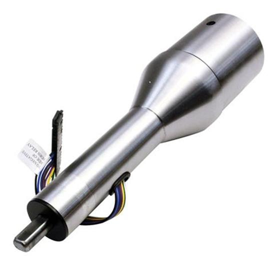
In-place of the standard 30" column, we will utilize a much shorter stubby Ididit steering column and a new product
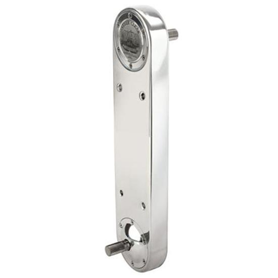
call the "Steer Clear". This is a way neat piece that allows the builder to Off-Set the steering
column over or around a problem area, which in our case is the floor area. We had always known the steering
was to be a very trying area. The heads and engine are so large that they take up all the room on each
side of the firewall, when the headers take-up all the room left over and even under the floor line, all of which was going
to make the steering connection between the column and the steering rack a real trying connection. With
all that has been going on, I simply decided to not even try to make the original 30" column work. It
was a no win situation, if I would have gotten it to connect, the steering would have been very lame with at least 4-5 universal
needed to connect the column to the steering rack. Then with the column going through the firewall/floorboard
area, it would have taken up way to much room and made the everyday operation of using the gas and brake pedals a real pain,
not to mention the lack of room for the dead pedal or left foot rest. I can avoid all this and gain back
the room, all by using the "Steer Clear". These pieces are available in several lengths, from
8" to 16" and come polished or brushed finished. This is the only real way around this delimbia.
The "Steer Clear" is a well made unit that comes complete and ready to install, they use steel cogs supported
by ball-bearings and chains to off-set the steering. The units are sealed and will never need service,
so they are perfect for this and many other steering problem issues. I have not determined the actual length
needed, but wouldn't be surprised to find I needed the longest or 16" unit. Because we had to
modify the firewall for the head clearance, I went ahead and sectioned the rear of the firewall as well, this will aid the
use of the "Steer Clear", by making this area flat so the "Steer Clear" can be solidly mounted there.
As of now, I am thinking about installing the "Steer Clear" in a way that would position the bottom joint
under all the congestion and make the final connection more straight and direct. Right now the main pieces
that are in the way are the Block/Head and Headers for a conventional hook-up. But, by lowering the "Steer
Clear" down and under the bottom of the floorboard, I can easily clear most obstacles, and in the process make the final
connection more straight forward and also use less universal joints in the process. This would make the
steering more driver friendly and precise. I won't know exactly what length we will need or weather
we will mount the unit on the inside or outside of the body till the sectioning is complete and we re-mount the body and check
for final clearances. Then and only then can we take the measurements needed to order the correct "Steer
Clear" for our project.
| Steer Clear Off-Set Steering Box |
|
| For many Hot Rodders, this is the only alternitive to the steering system blues. |
| Ididit Steering Column |
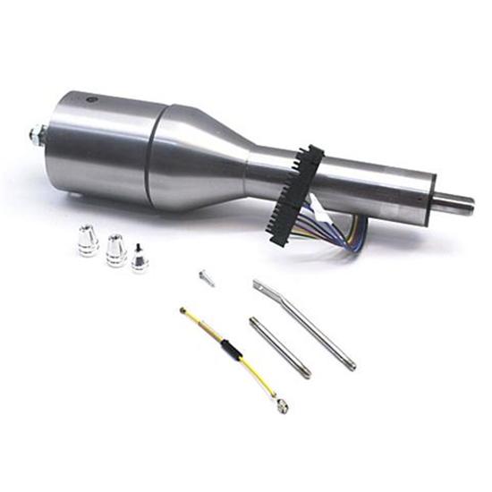
|
| This is the "Shorty" Steering Column that Ididit makes and what we will mostlikely end up using. |
|