|
|
 |
|
Frame Build-Up Part VIII
|
|
A
Little Background.....My web hosting provider has seen fit to change the operating system not just once but twice, in the
last 4 months. While they claim they are introducing a new and much better system, the bottom line is they are simply changing
things up so that the many features that once were included as Standard Features, will now be Optional Features and you will
now have to pay for those Features. There new and better slogan, is really simply a farce, and what they want is more money
and more control over what you can do with there server space you rent.
I tell you this because there
are some notable differences to the site. While I have been very busy trying to keep this site up and running, functioning
as normal as can be expected, there have been times certain pages were unavailable. I have managed to circumvent many of there
road blocks with good old fashioned horse sense, and on occasion some pretty neat back door trickery. While they have certainly
cost me many hours of typing and re-typing, I have managed to keep all the functions I have had, with-out the extra cost to
play in and on there new site. Something tells me that sooner or latter they will catch-on to my tricks and figure out a way
to shut me down, or at least make me pay the new rate, but until then....here we are...and here we will stay.
|
|
|
Enter content here
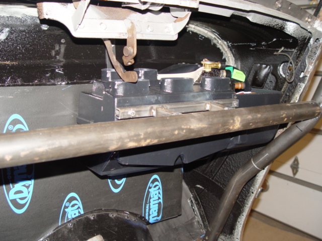
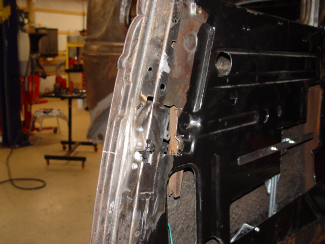
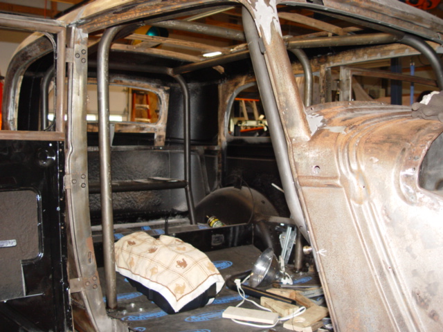
Heres the passenger side view, you can see how the front down-bar conforms to the dash and also the cross-member that runs
under the dash and connects the two sides. The AC Unit is supported in the back by the firewall and in the friont by
the cross-brace, We built a simple get strong mount out of 3/4" square tubing, that bolts to the side of the AC-unit
to support it. The AC-Unit can be removed by removeing the bolts and lowering the unit straight down.
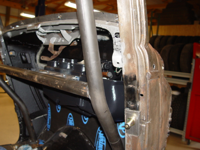
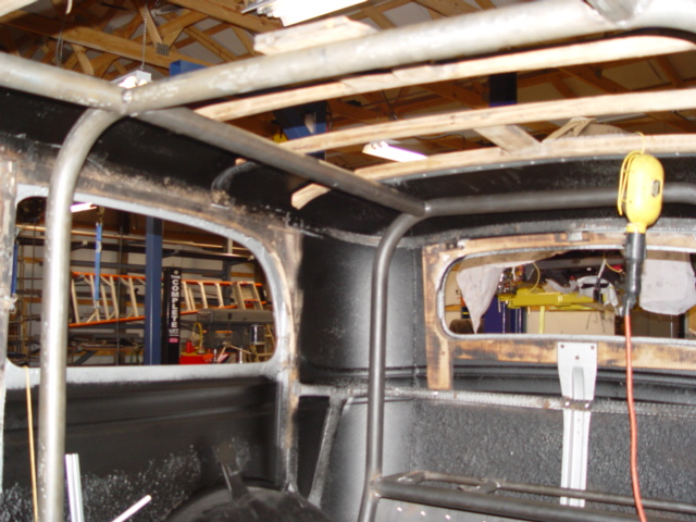
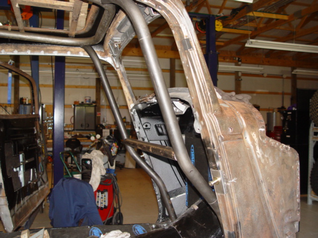
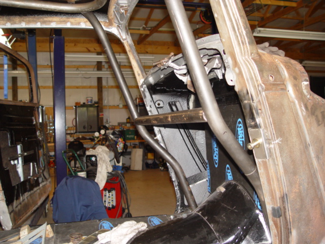
This like the previous pictures shows the AC-Unit and Passenger side roll bar. The form of the down bars is more evident
here, and you can also see the Bear Claw door stud we installed not so long ago. The latches work great, and I really
would recomend them to anyone wishing to up-grade there latches to better working, and much safer ones.
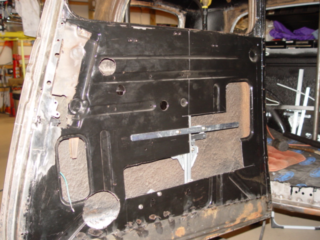
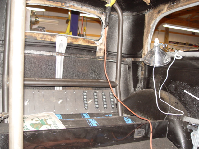
  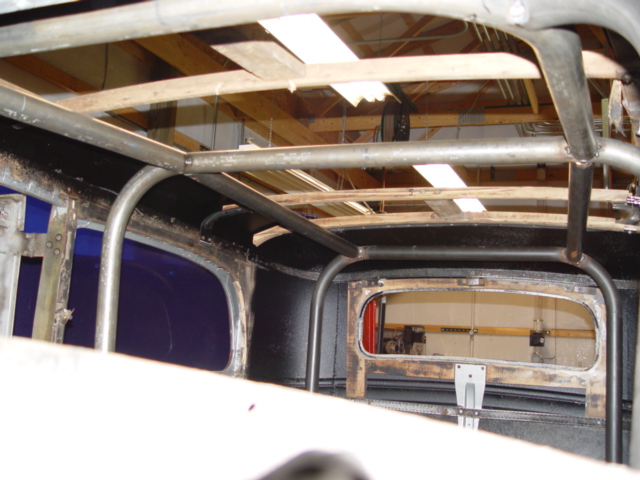 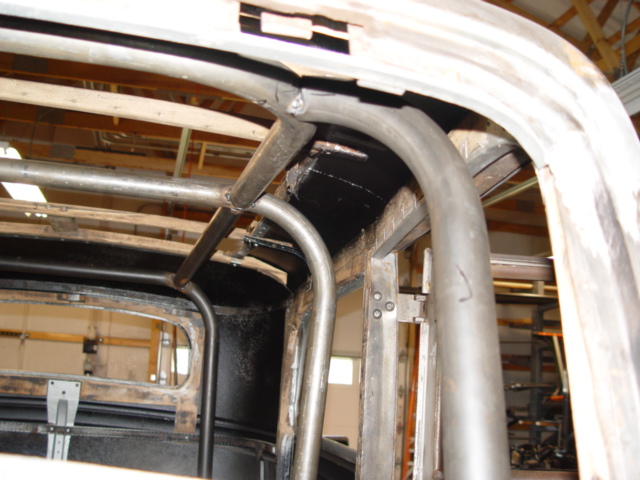 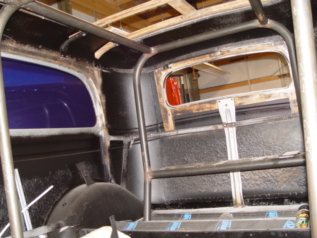 These
pictures all show different views of the roll cage, and body. You can see the wooden bows I metioned several times.
Like I said, I wished we could have gotten the roll bar a little closer fit to the wooden bows, but we had to leave room to
install them, and for the roof matterial and upolstry. The back Shelf will hold the battery, water tank and Sub Woofer
speaker. While the rear roll bar isn't perfect, it is much better then the rear hoop ideal we had.
The roll cage may be over-kill to some, and I would agree on many counts, but because of many things....like the fact the
car has a fabric roof, we will be making over 500 hourse-power and I would like to atleast try drag racing it some, I think
the roll cage is the right ideal. Yes it cuts down on interior room. Yes it takes a lot of time & Money to
construct. Yes it adds weight to the car. But it also adds a great measure of protection to the occupunts, really
strengthens the chasiss, and is used to support several major parts.
 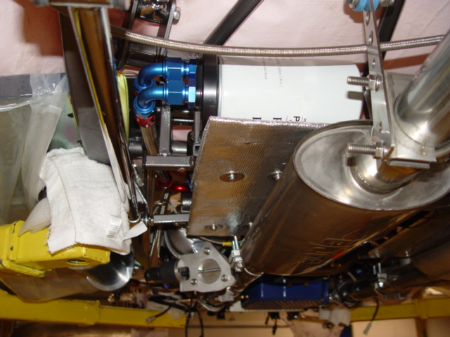 This
is a great shot of the drivers side rear frame view. You can see the remote oil filter and the heat-sheild we fabricated
to prevent the exhaust system from transfering heat to the oil filter. We addressed this issue several months ago, but
mainly we took a piece of 1/8" thick aluminum plate, added several layers of heat tape insulation (Header Warp) to both
sides, then covered it all with a sheet of reflective heat barrier(Termo-Tec). I have made other simular heat sheilds,
and all with very simular and succesful outcomes.
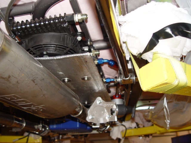 This
is the passenger side rear frame view. You can see the transmission cooler (it has the AN-8 lines attached) and the
inter-cooler cooler which is to the rear and does not have it's lines attached. Just below is the heat sheild we
made for this side, there is room between it's top and the coolers bottom to aid in air flow, but it will keep the
hot exhaust from seeping-up and into these two systems. Again all bolts/scres and fasteners are Stainless Steel on
Project'33
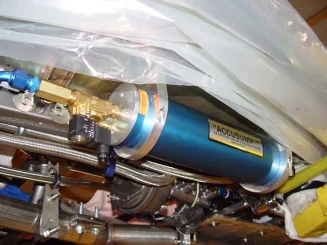
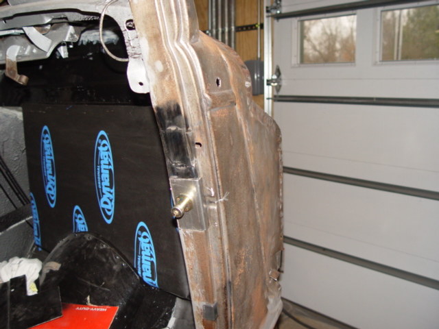
This
is our Accusump, from Canton. It is 3-quarts in size and I chose to use the billet aluminum mount to fasten it to the
bottom of the drivers side running board. The line feeding it is An-12 like the rest or the oiling system and it uses
a electric solinoid for for automatic control.
|
|
06-01-08
Before I moved the frame from the 2-Post lift to the 4-Post lift, where
it now rest, we did get a few things buttoned up. One such item was to re-route the oil lines from the engine adapter to the
oil filter and back to the cooler and accusump. While this was no big change, it was time consuming, I had to completely remove
the hoses and re-install them. The new installation, allowed for a better looking end product.
The hoses are now fully supports along there route and clamped
together with some very nice looking aluminum hose clamps, which keep the dressed side by side. The same goes for the other
side, I had to completely remove the transmission hoses and re-route them along the frame rail. Now the hoses look better
and fit the frame and space better, on both side I had to make adjustments to the length of several hoses. Keep this in mind
when you run your hoses. In hind sight, it would have been better
to completely leave the hoses alone, till the frame was completely ready for them, then run them one at a time along the frame rail from point "A" to point "B".
One great new item I finally got around to buying was a nice set of
cheater lenses for my welding hood. What a difference they make, way better they just wearing glasses under your hood, these
babies are crystal clear and I can now see. I am sure my welding will be much better from here on out, you can't weld
what you can't see!!!
I have been very busy around my house since
the first of the year, I decided to step a little further into the modular world, and build engines and cylinder heads for
others. I really fell in love with this engine and wanted to do more with it. I have been purchasing Teksid Aluminum blocks
and re-building them for re-sale to others. I have also decided to start re-building and modifying cylinder heads for the
modular engines. To help with the job, I purchased a valve seat grinder set-up and a valve face grinder set. This with several
other main tool sets will allow me to re-build and modify both 2, 3 and 4-valve heads. My goal is to simply offer great products
at fair prices, I am only concerned with the 4.6 and 5.4l engines and there heads. I have many neat ideals for these pieces
and have come up with several kits to make them stronger and easier to work on. You can read about them on this site by simply
clicking on the link that takes you to that part of the site.
06-02-08
We have been working on the dash, and the extended portion that spaces the front of the dash approximately 2-1/2" further
back then stock. I decided to add this section to the dash to allow us to install defrost ducts up next to the front window.
The benefits are obvious. Dad and I got the two new sections tach welded in place that spread the dash out. There are compound
type curves involved so the blanks took some time to get right, the welding was as usual, the easy part. The next step in
the dash dilemma, is to cap the ends and come up with a way to secure the two ends of the dash. I called the other day, and
dad has it worked out, just finishing up the fit.
Once the ends are capped, I want to get
started on the middle console. I have been thinking about it for some time, and once I get free to go down to the shop, I
can lay out all the pieces that go in the console and get it's final dimensions. We don't have tons of space, but
enough to do what I need done. The main point is to keep as much room between the console and seat fronts, and for the foot
area. No one wants to feel cramped in. Also, the design has to incorporate the theme of the car. I want it to look good and
be functional. We will also be designing and installing the roof console, that goes in the middle of the roof, from the front
windshield back about 12 inches. This console will house the rear view mirror and the overhead display.
Once the ends are capped, I want to get started on the middle console. I have been thinking about
it for some time, and once I get free to go down to the shop, I can lay out all the pieces that go in the console and get
it's final dimensions. We don't have tons of space, but enough to do what I need done. The main point is to keep as
much room between the console and seat fronts, and for the foot area. No one wants to feel cramped in. Also, the design has
to incorporate the theme of the car. I want it to look good and be functional. We will also be designing and installing the
roof console, that goes in the middle of the roof, from the front windshield back about 12 inches. This console will house
the rear view mirror and the overhead display.
Before I moved
the frame from the 2-Post lift to the 4-Post lift, where it now rest, we did get a few things buttoned up. One such item was
to re-route the oil lines from the engine adapter to the oil filter and back to the cooler and accusump. While this was no
big change, it was time consuming, I had to completely remove the hoses and re-install them. The new installation, allowed
for a better looking end product.
The hoses are now fully supports along there route and clamped together with some very nice looking aluminum hose clamps,
which keep the dressed side by side. The same goes for the other side, I had to completely remove the transmission hoses and
re-route them along the frame rail. Now the hoses look better and fit the frame and space better, on both side I had to make
adjustments to the length of several hoses. Keep this in mind when you run your hoses.
In hind sight, it would have been better to completely leave the hoses alone, till
the frame was completely ready for them, then run them one at a time along the
frame rail from point "A" to point "B".
One great
new item I finally got around to buying was a nice set of cheater lenses for my welding hood. What a difference they make,
way better they just wearing glasses under your hood, these babies are crystal clear and I can now see. I am sure my welding
will be much better from here on out, you can't weld what you can't see!!!
I have been very busy around my house since the first of the year, I decided to step a little further into the modular world,
and build engines and cylinder heads for others. I really fell in love with this engine and wanted to do more with it. I have
been purchasing Teksid Aluminum blocks and re-building them for re-sale to others. I have also decided to start re-building
and modifying cylinder heads for the modular engines. To help with the job, I purchased a valve seat grinder set-up and a
valve face grinder set. This with several other main tool sets will allow me to re-build and modify both 2, 3 and 4-valve
heads. My goal is to simply offer great products at fair prices, I am only concerned with the 4.6 and 5.4l engines and there
heads. I have many neat ideals for these pieces and have come up with several kits to make them stronger and easier to work
on. You can read about them on this site by simply clicking on the link that takes you to that part of the site.
06-02-08
We have been working on the dash, and the extended portion that
spaces the front of the dash approximately 2-1/2" further back then stock. I decided to add this section to the dash
to allow us to install defrost ducts up next to the front window. The benefits are obvious. Dad and I got the two new sections
tach welded in place that spread the dash out. There are compound type curves involved so the blanks took some time to get
right, the welding was as usual, the easy part. The next step in the dash dilemma, is to cap the ends and come up with a way
to secure the two ends of the dash. I called the other day, and dad has it worked out, just finishing up the fit.
Once the ends are capped, I want to get started on the middle console. I have been thinking about it for some time, and once
I get free to go down to the shop, I can lay out all the pieces that go in the console and get it's final dimensions.
We don't have tons of space, but enough to do what I need done. The main point is to keep as much room between the console
and seat fronts, and for the foot area. No one wants to feel cramped in. Also, the design has to incorporate the theme of
the car. I want it to look good and be functional. We will also be designing and installing the roof console, that goes in
the middle of the roof, from the front windshield back about 12 inches. This console will house the rear view mirror and the
overhead display.
Once the ends are capped, I want to get started on
the middle console. I have been thinking about it for some time, and once I get free to go down to the shop, I can lay out
all the pieces that go in the console and get it's final dimensions. We don't have tons of space, but enough to do
what I need done. The main point is to keep as much room between the console and seat fronts, and for the foot area. No one
wants to feel cramped in. Also, the design has to incorporate the theme of the car. I want it to look good and be functional.
We will also be designing and installing the roof console, that goes in the middle of the roof, from the front windshield
back about 12 inches. This console will house the rear view mirror and the overhead display.
Before I moved the frame from the 2-Post lift to the 4-Post lift, where
it now rest, we did get a few things buttoned up. One such item was to re-route the oil lines from the engine adapter to the
oil filter and back to the cooler and accusump. While this was no big change, it was time consuming, I had to completely remove
the hoses and re-install them. The new installation, allowed for a better looking end product. The hoses are now fully supports
along there route and clamped together with some very nice looking aluminum hose clamps, which keep the dressed side by side.
The same goes for the other side, I had to completely remove the transmission hoses and re-route them along the frame rail.
Now the hoses look better and fit the frame and space better, on both side I had to make adjustments to the length of several
hoses. Keep this in mind when you run your hoses. In hind sight, it would have been better to completely leave the hoses alone,
till the frame was completely ready for them, then run them one at a time along the frame rail from point "A" to
point "B".
One great new item I finally got around to buying was a nice set of cheater lenses
for my welding hood. What a difference they make, way better they just wearing glasses under your hood, these babies are crystal
clear and I can now see. I am sure my welding will be much better from here on out, you can't weld what you can't
see!!!
I have been very busy around my house since the first of the year,
I decided to step a little further into the modular world, and build engines and cylinder heads for others. I really fell
in love with this engine and wanted to do more with it. I have been purchasing Teksid Aluminum blocks and re-building them
for re-sale to others. I have also decided to start re-building and modifying cylinder heads for the modular engines. To help
with the job, I purchased a valve seat grinder set-up and a valve face grinder set. This with several other main tool sets
will allow me to re-build and modify both 2, 3 and 4-valve heads. My goal is to simply offer great products at fair prices,
I am only concerned with the 4.6 and 5.4l engines and there heads. I have many neat ideals for these pieces and have come
up with several kits to make them stronger and easier to work on. You can read about them on this site by simply clicking
on the link that takes you to that part of the site.
06-02-08
We have been working on the dash,
and the extended portion that spaces the front of the dash approximately 2-1/2" further back then stock. I decided to
add this section to the dash to allow us to install defrost ducts up next to the front window. The benefits are obvious. Dad
and I got the two new sections tach welded in place that spread the dash out. There are compound type curves involved so the
blanks took some time to get right, the welding was as usual, the easy part. The next step in the dash delama, is to cap the
ends and come up with a way to secure the two ends of the dash. I called the other day, and dad has it worked out, just finishing
up the fit.
Once the ends are capped, I want to get started on the middle
console. I have been thinking about it for some time, and once I get free to go down to the shop, I can lay out all the pieces
that go in the console and get it's final dimensions. We don't have tons of space, but enough to do what I need done.
The main point is to keep as much room between the console and seat fronts, and for the foot area. No one wants to feel cramped
in. Also, the design has to incorporate the theme of the car. I want it to look good and be functional. We will also be designing
and installing the roof console, that goes in the middle of the roof, from the front windshield back about 12 inches. This
console will house the rear view mirror and the overhead display.
06-10-08
Wow, I
have to get back into the spirit of working on the car, being away for a while like I was, makes you rusty.
The dash is all but finished, at least the modifications we made to it are. It turned out real nice, the section we installed
to widen it 2-1/2" looks nice, and Dad came up with a really cool way to cap off the ends and secure it. I removed it
and welded up the back side, just before we sanded down the front and removed 90% of the weld material. We had no warp-age
issues to address, which is good, and the whole thing was a positive experience. It looks right at home installed in the body,
but is different enough to draw attention, sound perfect to me !!.. One feature we worked hard on, was to make it easy to
install and uninstall from the body, and we were successful. Things get much more difficult with a roll cage to build around,
but it is possible to still make things right. It all just takes time and patients.
The defrost ducts, which were of coarse the reason we added the width to the dash, are in and went fine. We made the openings
much larger then those I have seen, most time others just cut a small 3/8" or 1/2" x 3" opening. I understand
why they do this, but it doesn't serve as a very good defrost duck with this small of an opening, so we cut an almost
full width and length opening in our dash, this way we will get plenty of flow and hopefully will be able to drive in the
rain. I am looking for some type of material to use as a screen, something like a heavy stainless steel material that is woven,
think HD screen or industrial sifter type material. I'll let you know when I find something. We have this option because
our dash is wider.
One item I got going was the door bars and seat back
bar. These items have to be removable, because they would severely limit the inside room and access, but are necessary for
competition. In order to make things as easy and nice as possible, I am using what is called a door bar kit. These items can
be purchased from most chassis builders and race shops, our came from S &W Race Cars and are unique in that they have
a center round tube that goes through the roll cage and gets welded in place. This tube serves as a stiffener and after welding,
replenishes the strength of the roll cage, were others simply leave a hole. The hole is there for the attachment to the roll
cage, so the door bars or rear seat back bar can be removed or installed quickly and easily, by simply installing a bolt or
quick release pin. This tube they sell with there door bar kits, serves to restore the integrity of the roll cage, where simply
drilling a 3/4" hole into the 1-5/8" tube would severely limit it's strength. I did modify our door bar kits
to accommodate our needs, the normal way to mount them would require a stub of the same diameter tubing be welded to the main
structure or roll cage. This stub which would have to be at least 3" in length, would serve as the foundation for the
door bar, but because I did not want anything sticking out from the roll cage that would limit or hinder front or rear seat
access, I modified the door bar kits, by drilling a relief in them so they would now fit over the existing roll cage and mount
without the stub. All that was needed was to drill with a hole saw, roughly the size of the roll cage material which in our
case is 1-5/8' tube, a relief in the edge of the door bar bracket so the new bracket will now wrap around the roll cage
bar instead of but up to it. To get this done, I had to tach weld the two pieces together, when drill a 1/4" pilot hole
in the right spot, when follow up with the hole saw. I'll post some pictures later to clarify the procedure. The benefit
of doing it like this is now the door bars and seat back bar will easily install and remove from the car and there is nothing
on the roll cage to snag or poke you as you enter or exist the car. These kits come in a package of two, with one push-pin
connector and one bolt and the four attachment halves. To do what we did would require three door bar kits, and they run about
$39.99 each kit. I have already ordered extra push-pins to eliminate the use of the bolts, now all the attachment will be
by push-pins, which will be much nicer to install and remove the bars.
Another small projects I worked on was to permanently attach the running boards. I had attached them with just a few bolts
to mock-up the Accusump oil sump, but now I need to go ahead and install all the hardware and bolt them up for good. First
I had to temporarily remove the Accusump to access the area. Next the running board metal braces we painted to match the frame
were installed, these I drilled out to accept a 3/8" bolt, and installed with all stainless steel hardware. They have
one 3/8" x 1" bolt that mount to the bottom of the frame, and then another 3/8" x 2" bolt that mounts
to the running boards, in a double sheer orientation that really adds some strength to the set-up. The rest of the running
board mounting bolts simply attach to the side of the frame, there are three bolts that support each brace and four bolts
that attach to the sides, that makes 14 3/8" bolts hold each running board on....I don't think their going any place!.!
I was simply amazed that everything aligned, I had been worried that there would be alignment issues but that wasn't even
an issue, they bolted right up, I only had to use a tapered alignment pin to bring everything together, wow what a great day!!!
Of-coarse I could not step on the newly installed running boards, but I did pull down on them and they seemed to be very stout.
I was worried because we had boxed the frame rails, and before I did that, I welded nuts to the back sides of the frame rails
so we could attached these running boards, the problem was there was no way to make-up for anything being off, not even a
little bit. We were locked into this location, and with the running boards being manufactured by one makers and the frame
by another, I was really worried about small differences that would add up against us. I can't tell you how relived I
was to see those running boards on and fitting like they should.
One little item I also got finished was I wrapped some
of the braided hoses that were close to the frame rails with a plastic wire loom material. I wanted to wrap them because braided
hose looks great and performed wonderfully, but they are very abrasive. While I have used hose separators and hose clamps
to keep the hose in place, there are still areas where the hose would rub the frame or other parts when driving, it's
these areas that I wrapped with the wire loom to keep from messing up the paint or other finish. I simply identified the problem
areas and then wrapped the hoses to protect the finishes from damage. You also want to avoid running wires along with hoses,
the abrasive hoses will eat right though the insulation on the wires allowing for a short circuit.
Back to the dash console......Wow this one item proved to be more difficult then I first thought.
My initial design was to make a spear like console, once I bent it up in the bender and compared it in the car, it was way
to big and interfered with the shifter and E brake handle. Design Number 2.....this time I made a more narrow and wider console,
I bent the pieces on the tube bender and assembled it on the bench, Oh..I am using 3/4" square tubing, 16 gauge for the
frame work on the console. This time I got the right dimensions but the initial mounting location was off. On to design Number
three...We removed the console and proceeded to change the mounting location to move it back further under the dash. We also
had to cut off part of the passenger side rear frame, to clear the Vintage Air AC unit. Now with the mounts located in the
very front, the console fit much better, there was way more knee room for the driver and the unit looked better tucked up
and back in under the dash. We used the under dash bar from the roll cage to mount the console, which also mounts the AC unit.
I welded on two tabs that hang down from the bottom of the bar to bolt to the sides of the console, which allow it to be removed
very easily. Now that we have a keeper, we marked out the face plate which was 1/8" flat sheet metal and cut it out and
trimmed it up to fit, then I drilled the mounting holes all seven of them and tapped the console for 10-32 mounting screws.
With the face plate looking great, we moved on to the outside skin of the console, here we used a piece of 20 gauge sheet
metal and formed it around the frame work of the console, tach welding it in place as we formed it. This was the quickest
part of the whole process, and in no time we had our console almost finished. We left plenty of material on each side, that
we will now trim off. This is where I left it, Dad will do the trimming latter on and we will also have to mark and trim the
openings in the face plate, but for now I'm leaving it bare. In all, I didn't quite get the room I wanted, but we
did get the console that best fits and matches the car, so I suppose that is the main thing. I have so many systems and Sub-systems
on this car that there just isn't enough room to properly mount all of them, or it doesn't seem that way now, maybe
things will change for the better as we get closer to the final product?.?.?
Project Cobra'33 is
really starting to come around, it won't be that long till we start in on the body work and paint preparations. From there,
we need to install the over head roll cage bars and console, then get the front seat mounted and in the proper place. Once
that is finished we can remove the front and rear halves of the roll cage and finish welding the front section. Remove the
seats and dash then go over the exterior of the body with our sand blaster and then apply a good base coat of epoxy primer,
and let the body work commence.
One great new item I finally got around to
buying was a nice set of cheater lenses for my welding hood. What a difference they make, way better they just wearing glasses
under your hood, these babies are crystal clear and I can now see. I am sure my welding will be much better from here on out,
you can't weld what you can't see!!!
I have been very busy around
my house since the first of the year, I decided to step a little further into the modular world, and build engines and cylinder
heads for others. I really fell in love with this engine and wanted to do more with it. I have been purchasing Teksid Aluminum
blocks and re-building them for re-sale to others. I have also decided to start re-building and modifying cylinder heads for
the modular engines. To help with the job, I purchased a valve seat grinder set-up and a valve face grinder set. This with
several other main tool sets will allow me to re-build and modify both 2, 3 and 4-valve heads. My goal is to simply offer
great products at fair prices, I am only concerned with the 4.6 and 5.4l engines and there heads. I have many neat ideals
for these pieces and have come up with several kits to make them stronger and easier to work on. You can read about them on
this site by simply clicking on the link that takes you to that part of the site.
06-02-08
We have been working on the dash, and the extended portion that spaces the front of the dash approximately 2-1/2" further
back then stock. I decided to add this section to the dash to allow us to install defrost ducts up next to the front window.
The benefits are obvious. Dad and I got the two new sections tach welded in place that spread the dash out. There are compound
type curves involved so the blanks took some time to get right, the welding was as usual, the easy part. The next step in
the dash delama, is to cap the ends and come up with a way to secure the two ends of the dash. I called the other day, and
dad has it worked out, just finishing up the fit.
Once the ends are capped,
I want to get started on the middle console. I have been thinking about it for some time, and once I get free to go down to
the shop, I can lay out all the pieces that go in the console and get it's final dimensions. We don't have tons of
space, but enough to do what I need done. The main point is to keep as much room between the console and seat fronts, and
for the foot area. No one wants to feel cramped in. Also, the design has to incorporate the theme of the car. I want it to
look good and be functional. We will also be designing and installing the roof console, that goes in the middle of the roof,
from the front windshield back about 12 inches. This console will house the rear view mirror and the overhead display.
06-10-08
Wow, I have to get back into the spirit of working on the car, being away for
a while like I was, makes you rusty.
The dash is all but finished, at least the modifications
we made to it are. It turned out real nice, the section we installed to widen it 2-1/2" looks nice, and Dad came up with
a really cool way to cap off the ends and secure it. I removed it and welded up the back side, just before we sanded down
the front and removed 90% of the weld material. We had no warp-age issues to address, which is good, and the whole thing was
a positive experience. It looks right at home installed in the body, but is different enough to draw attention, sound perfect
to me !!.. One feature we worked hard on, was to make it easy to install and uninstall from the body, and we were successful.
Things get much more difficult with a roll cage to build around, but it is possible to still make things right. It all just
takes time and patients.
The defrost ducts, which were of coarse the reason we
added the width to the dash, are in and went fine. We made the openings much larger then those I have seen, most time others
just cut a small 3/8" or 1/2" x 3" opening. I understand why they do this, but it doesn't serve as a very
good defrost duck with this small of an opening, so we cut an almost full width and length opening in our dash, this way we
will get plenty of flow and hopefully will be able to drive in the rain. I am looking for some type of material to use as
a screen, something like a heavy stainless steel material that is woven, think HD screen or industrial sifter type material.
I'll let you know when I find something. We have this option because our dash is wider.
One item I got going was the door bars and seat back bar. These items have to be removable, because they would severely limit
the inside room and access, but are necessary for competition. In order to make things as easy and nice as possible, I am
using what is called a door bar kit. These items can be purchased from most chassis builders and race shops, our came from
S &W Race Cars and are unique in that they have a center round tube that goes through the roll cage and gets welded in
place. This tube serves as a stiffener and after welding, replenishes the strength of the roll cage, were others simply leave
a hole. The hole is there for the attachment to the roll cage, so the door bars or rear seat back bar can be removed or installed
quickly and easily, by simply installing a bolt or quick release pin. This tube they sell with there door bar kits, serves
to restore the integrity of the roll cage, where simply drilling a 3/4" hole into the 1-5/8" tube would severely
limit it's strength. I did modify our door bar kits to accommodate our needs, the normal way to mount them would require
a stub of the same diameter tubing be welded to the main structure or roll cage. This stub which would have to be at least
3" in length, would serve as the foundation for the door bar, but because I did not want anything sticking out from the
roll cage that would limit or hinder front or rear seat access, I modified the door bar kits, by drilling a relief in them
so they would now fit over the existing roll cage and mount without the stub. All that was needed was to drill with a hole
saw, roughly the size of the roll cage material which in our case is 1-5/8' tube, a relief in the edge of the door bar
bracket so the new bracket will now wrap around the roll cage bar instead of but up to it. To get this done, I had to tach
weld the two pieces together, when drill a 1/4" pilot hole in the right spot, when follow up with the hole saw. I'll
post some pictures later to clarify the procedure. The benefit of doing it like this is now the door bars and seat back bar
will easily install and remove from the car and there is nothing on the roll cage to snag or poke you as you enter or exist
the car. These kits come in a package of two, with one push-pin connector and one bolt and the four attachment halves. To
do what we did would require three door bar kits, and they run about $39.99 each kit. I have already ordered extra push-pins
to eliminate the use of the bolts, now all the attachment will be by push-pins, which will be much nicer to install and remove
the bars.
Another small projects I worked on was to permanently
attach the running boards. I had attached them with just a few bolts to mock-up the Accusump oil sump, but now I need to go
ahead and install all the hardware and bolt them up for good. First I had to temporarily remove the Accusump to access the
area. Next the running board metal braces we painted to match the frame were installed, these I drilled out to accept a 3/8"
bolt, and installed with all stainless steel hardware. They have one 3/8" x 1" bolt that mount to the bottom of
the frame, and then another 3/8" x 2" bolt that mounts to the running boards, in a double sheer orientation that
really adds some strength to the set-up. The rest of the running board mounting bolts simply attach to the side of the frame,
there are three bolts that support each brace and four bolts that attach to the sides, that makes 14 3/8" bolts hold
each running board on....I don't think their going any place!.! I was simply amazed that everything aligned, I had been
worried that there would be alignment issues but that wasn't even an issue, they bolted right up, I only had to use a
tapered alignment pin to bring everything together, wow what a great day!!! Of-coarse I could not step on the newly installed
running boards, but I did pull down on them and they seemed to be very stout. I was worried because we had boxed the frame
rails, and before I did that, I welded nuts to the back sides of the frame rails so we could attached these running boards,
the problem was there was no way to make-up for anything being off, not even a little bit. We were locked into this location,
and with the running boards being manufactured by one makers and the frame by another, I was really worried about small differences
that would add up against us. I can't tell you how relived I was to see those running boards on and fitting like they
should.
One little item I also got finished was I wrapped some of the braided hoses that were close to the frame rails
with a plastic wire loom material. I wanted to wrap them because braided hose looks great and performed wonderfully, but they
are very abrasive. While I have used hose separators and hose clamps to keep the hose in place, there are still areas where
the hose would rub the frame or other parts when driving, it's these areas that I wrapped with the wire loom to keep from
messing up the paint or other finish. I simply identified the problem areas and then wrapped the hoses to protect the finishes
from damage. You also want to avoid running wires along with hoses, the abrasive hoses will eat right though the insulation
on the wires allowing for a short circuit.
Back to the dash console......Wow
this one item proved to be more difficult then I first thought. My initial design was to make a spear like console, once I
bent it up in the bender and compared it in the car, it was way to big and interfered with the shifter and E brake handle.
Design Number 2.....this time I made a more narrow and wider console, I bent the pieces on the tube bender and assembled it
on the bench, Oh..I am using 3/4" square tubing, 16 gauge for the frame work on the console. This time I got the right
dimensions but the initial mounting location was off. On to design Number three...We removed the console and proceeded to
change the mounting location to move it back further under the dash. We also had to cut off part of the passenger side rear
frame, to clear the Vintage Air AC unit. Now with the mounts located in the very front, the console fit much better, there
was way more knee room for the driver and the unit looked better tucked up and back in under the dash. We used the under dash
bar from the roll cage to mount the console, which also mounts the AC unit. I welded on two tabs that hang down from the bottom
of the bar to bolt to the sides of the console, which allow it to be removed very easily. Now that we have a keeper, we marked
out the face plate which was 1/8" flat sheet metal and cut it out and trimmed it up to fit, then I drilled the mounting
holes all seven of them and tapped the console for 10-32 mounting screws. With the face plate looking great, we moved on to
the outside skin of the console, here we used a piece of 20 gauge sheet metal and formed it around the frame work of the console,
tach welding it in place as we formed it. This was the quickest part of the whole process, and in no time we had our console
almost finished. We left plenty of material on each side, that we will now trim off. This is where I left it, Dad will do
the trimming latter on and we will also have to mark and trim the openings in the face plate, but for now I'm leaving
it bare. In all, I didn't quite get the room I wanted, but we did get the console that best fits and matches the car,
so I suppose that is the main thing. I have so many systems and Sub-systems on this car that there just isn't enough room
to properly mount all of them, or it doesn't seem that way now, maybe things will change for the better as we get closer
to the final product?.?.?
Project
Cobra'33 is really starting
to come around, it won't be that long till we start in on the body work and paint preparations. From there, we need to
install the over head roll cage bars and console, then get the front seat mounted and in the proper place. Once that is finished
we can remove the front and rear halves of the roll cage and finish welding the front section. Remove the seats and dash then
go over the exterior of the body with our sand blaster and then apply a good base coat of epoxy primer, and let the body work
commence.
06-10-08
Wow, I have to get back into the spirit of
working on the car, being away for a while like I was, makes you rusty.
The dash is all but
finished, at least the modifications we made to it are. It turned out real nice, the section we installed to widen it 2-1/2"
looks nice, and Dad came up with a really cool way to cap off the ends and secure it. I removed it and welded up the back
side, just before we sanded down the front and removed 90% of the weld material. We had no warp-age issues to address, which
is good, and the whole thing was a positive experience. It looks right at home installed in the body, but is different enough
to draw attention, sound perfect to me !!.. One feature we worked hard on, was to make it easy to install and uninstall from
the body, and we were successful. Things get much more difficult with a roll cage to build around, but it is possible to still
make things right. It all just takes time and patients.
The defrost ducts, which
were of coarse the reason we added the width to the dash, are in and went fine. We made the openings much larger then those
I have seen, most time others just cut a small 3/8" or 1/2" x 3" opening. I understand why they do this, but
it doesn't serve as a very good defrost duck with this small of an opening, so we cut an almost full width and length
opening in our dash, this way we will get plenty of flow and hopefully will be able to drive in the rain. I am looking for
some type of material to use as a screen, something like a heavy stainless steel material that is woven, think HD screen or
industrial sifter type material. I'll let you know when I find something. We have this option because our dash is wider.
One item I got going was the door bars and seat back bar. These items have
to be removable, because they would severely limit the inside room and access, but are necessary for competition. In order
to make things as easy and nice as possible, I am using what is called a door bar kit. These items can be purchased from most
chassis builders and race shops, our came from S &W Race Cars and are unique in that they have a center round tube that
goes through the roll cage and gets welded in place. This tube serves as a stiffener and after welding, replenishes the strength
of the roll cage, were others simply leave a hole. The hole is there for the attachment to the roll cage, so the door bars
or rear seat back bar can be removed or installed quickly and easily, by simply installing a bolt or quick release pin. This
tube they sell with there door bar kits, serves to restore the integrity of the roll cage, where simply drilling a 3/4"
hole into the 1-5/8" tube would severely limit it's strength. I did modify our door bar kits to accommodate our needs,
the normal way to mount them would require a stub of the same diameter tubing be welded to the main structure or roll cage.
This stub which would have to be at least 3" in length, would serve as the foundation for the door bar, but because I
did not want anything sticking out from the roll cage that would limit or hinder front or rear seat access, I modified the
door bar kits, by drilling a relief in them so they would now fit over the existing roll cage and mount without the stub.
All that was needed was to drill with a hole saw, roughly the size of the roll cage material which in our case is 1-5/8'
tube, a relief in the edge of the door bar bracket so the new bracket will now wrap around the roll cage bar instead of but
up to it. To get this done, I had to tach weld the two pieces together, when drill a 1/4" pilot hole in the right spot,
when follow up with the hole saw. I'll post some pictures later to clarify the procedure. The benefit of doing it like
this is now the door bars and seat back bar will easily install and remove from the car and there is nothing on the roll cage
to snag or poke you as you enter or exist the car. These kits come in a package of two, with one push-pin connector and one
bolt and the four attachment halves. To do what we did would require three door bar kits, and they run about $39.99 each kit.
I have already ordered extra push-pins to eliminate the use of the bolts, now all the attachment will be by push-pins, which
will be much nicer to install and remove the bars.
Another
small projects I worked on was to permanently attach the running boards. I had attached them with just a few bolts to mock-up
the Accusump oil sump, but now I need to go ahead and install all the hardware and bolt them up for good. First I had to temporarily
remove the Accusump to access the area. Next the running board metal braces we painted to match the frame were installed,
these I drilled out to accept a 3/8" bolt, and installed with all stainless steel hardware. They have one 3/8" x
1" bolt that mount to the bottom of the frame, and then another 3/8" x 2" bolt that mounts to the running boards,
in a double sheer orientation that really adds some strength to the set-up. The rest of the running board mounting bolts simply
attach to the side of the frame, there are three bolts that support each brace and four bolts that attach to the sides, that
makes 14 3/8" bolts hold each running board on....I don't think their going any place!.! I was simply amazed that
everything aligned, I had been worried that there would be alignment issues but that wasn't even an issue, they bolted
right up, I only had to use a tapered alignment pin to bring everything together, wow what a great day!!! Of-coarse I could
not step on the newly installed running boards, but I did pull down on them and they seemed to be very stout. I was worried
because we had boxed the frame rails, and before I did that, I welded nuts to the back sides of the frame rails so we could
attached these running boards, the problem was there was no way to make-up for anything being off, not even a little bit.
We were locked into this location, and with the running boards being manufactured by one makers and the frame by another,
I was really worried about small differences that would add up against us. I can't tell you how relived I was to see those
running boards on and fitting like they should.
One little item I also got finished was I wrapped some of the braided
hoses that were close to the frame rails with a plastic wire loom material. I wanted to wrap them because braided hose looks
great and performed wonderfully, but they are very abrasive. While I have used hose separators and hose clamps to keep the
hose in place, there are still areas where the hose would rub the frame or other parts when driving, it's these areas
that I wrapped with the wire loom to keep from messing up the paint or other finish. I simply identified the problem areas
and then wrapped the hoses to protect the finishes from damage. You also want to avoid running wires along with hoses, the
abrasive hoses will eat right though the insulation on the wires allowing for a short circuit.
Back to the dash console......Wow this one item proved to be more difficult then I first thought. My initial design was to
make a spear like console, once I bent it up in the bender and compared it in the car, it was way to big and interfered with
the shifter and E brake handle. Design Number 2.....this time I made a more narrow and wider console, I bent the pieces on
the tube bender and assembled it on the bench, Oh..I am using 3/4" square tubing, 16 gauge for the frame work on the
console. This time I got the right dimensions but the initial mounting location was off. On to design Number three...We removed
the console and proceeded to change the mounting location to move it back further under the dash. We also had to cut off part
of the passenger side rear frame, to clear the Vintage Air AC unit. Now with the mounts located in the very front, the console
fit much better, there was way more knee room for the driver and the unit looked better tucked up and back in under the dash.
We used the under dash bar from the roll cage to mount the console, which also mounts the AC unit. I welded on two tabs that
hang down from the bottom of the bar to bolt to the sides of the console, which allow it to be removed very easily. Now that
we have a keeper, we marked out the face plate which was 1/8" flat sheet metal and cut it out and trimmed it up to fit,
then I drilled the mounting holes all seven of them and tapped the console for 10-32 mounting screws. With the face plate
looking great, we moved on to the outside skin of the console, here we used a piece of 20 gauge sheet metal and formed it
around the frame work of the console, tach welding it in place as we formed it. This was the quickest part of the whole process,
and in no time we had our console almost finished. We left plenty of material on each side, that we will now trim off. This
is where I left it, Dad will do the trimming latter on and we will also have to mark and trim the openings in the face plate,
but for now I'm leaving it bare. In all, I didn't quite get the room I wanted, but we did get the console that best
fits and matches the car, so I suppose that is the main thing. I have so many systems and Sub-systems on this car that there
just isn't enough room to properly mount all of them, or it doesn't seem that way now, maybe things will change for
the better as we get closer to the final product?.?.?
Project Cobra'33 is
really starting to come around, it won't be that long till we start in on the body work and paint preparations. From there,
we need to install the over head roll cage bars and console, then get the front seat mounted and in the proper place. Once
that is finished we can remove the front and rear halves of the roll cage and finish welding the front section. Remove the
seats and dash then go over the exterior of the body with our sand blaster and then apply a good base coat of epoxy primer,
and let the body work commence.
Project
Cobra'33 is really starting
to come around, it won't be that long till we start in on the body work and paint preparations. From there, we need to
install the over head roll cage bars and console, then get the front seat mounted and in the proper place. Once that is finished
we can remove the front and rear halves of the roll cage and finish welding the front section. Remove the seats and dash then
go over the exterior of the body with our sand blaster and then apply a good base coat of epoxy primer, and let the body work
commence.
One great new item I finally got around to buying was a nice set of cheater lenses for my
welding hood. What a difference they make, way better they just wearing glasses under your hood, these babies are crystal
clear and I can now see. I am sure my welding will be much better from here on out, you can't weld what you can't
see!!!
I have been very busy around my house since the first of the
year, I decided to step a little further into the modular world, and build engines and cylinder heads for others. I really
fell in love
with this engine and wanted to do more with it. I have been purchasing Teksid Aluminum blocks and re-building them for re-sale
to others. I have also decided to start re-building and modifying cylinder heads for the modular engines. To help with the
job, I purchased a valve seat grinder set-up and a valve face grinder set. This with several other main tool sets will allow
me to re-build and modify both 2, 3 and 4-valve heads. My goal is to simply offer great products at fair prices, I am only
concerned with the 4.6 and 5.4l engines and there heads. I have many neat ideals for these pieces and have come up with several
kits to make them stronger and easier to work on. You can read about them on this site by simply clicking on the link that
takes you to that part of the site.
06-02-08
We have been working on the dash, and the extended portion that spaces the front of the dash approximately 2-1/2" further
back then stock. I decided to add this section to the dash to allow us to install defrost ducts up next to the front window.
The benefits are obvious. Dad and I got the two new sections tach welded in place that spread the dash out. There are compound
type curves involved so the blanks took some time to get right, the welding was as usual, the easy part. The next step in
the dash delama, is to cap the ends and come up with a way to secure the two ends of the dash. I called the other day, and
dad has it worked out, just finishing up the fit.
Once the ends are capped, I want to get
started on the middle console. I have been thinking about it for some time, and once I get free to go down to the shop, I
can lay out all the pieces that go in the console and get it's final dimensions. We don't have tons of space, but
enough to do what I need done. The main point is to keep as much room between the console and seat fronts, and for the foot
area. No one wants to feel cramped in. Also, the design has to incorporate the theme of the car. I want it to look good and
be functional. We will also be designing and installing the roof console, that goes in the middle of the roof, from the front
windshield back about 12 inches. This console will house the rear view mirror and the overhead display.
One great new item I finally got around
to buying was a nice set of cheater lenses for my welding hood. What a difference they make, way better they just wearing
glasses under your hood, these babies are crystal clear and I can now see. I am sure my welding will be much better from here
on out, you can't weld what you can't see!!!
I have been very
busy around my house since the first of the year, I decided to step a little further into the modular world, and build engines
and cylinder heads for others. I really fell in love with this engine and wanted to do more with it. I have been purchasing Teksid Aluminum blocks
and re-building them for re-sale to others. I have also decided to start re-building and modifying cylinder heads for the
modular engines. To help with the job, I purchased a valve seat grinder set-up and a valve face grinder set. This with several
other main tool sets will allow me to re-build and modify both 2, 3 and 4-valve heads. My goal is to simply offer great products
at fair prices, I am only concerned with the 4.6 and 5.4l engines and there heads. I have many neat ideals for these pieces
and have come up with several kits to make them stronger and easier to work on. You can read about them on this site by simply
clicking on the link that takes you to that part of the site.
06-02-08
We have been working on the dash, and the extended portion that spaces the front of the dash approximately 2-1/2" further
back then stock. I decided to add this section to the dash to allow us to install defrost ducts up next to the front window.
The benefits are obvious. Dad and I got the two new sections tach welded in place that spread the dash out. There are compound
type curves involved so the blanks took some time to get right, the welding was as usual, the easy part. The next step in
the dash delama, is to cap the ends and come up with a way to secure the two ends of the dash. I called the other day, and
dad has it worked out, just finishing up the fit.
Once the ends are capped, I want to get
started on the middle console. I have been thinking about it for some time, and once I get free to go down to the shop, I
can lay out all the pieces that go in the console and get it's final dimensions. We don't have tons of space, but
enough to do what I need done. The main point is to keep as much room between the console and seat fronts, and for the foot
area. No one wants to feel cramped in. Also, the design has to incorporate the theme of the car. I want it to look good and
be functional. We will also be designing and installing the roof console, that goes in the middle of the roof, from the front
windshield back about 12 inches. This console will house the rear view mirror and the overhead display.
love with this
engine and wanted to do more with it. I have been purchasing Teksid Aluminum blocks and re-building them for re-sale to others.
I have also decided to start re-building and modifying cylinder heads for the modular engines. To help with the job, I purchased
a valve seat grinder set-up and a valve face grinder set. This with several other main tool sets will allow me to re-build
and modify both 2, 3 and 4-valve heads. My goal is to simply offer great products at fair prices, I am only concerned with
the 4.6 and 5.4l engines and there heads. I have many neat ideals for these pieces and have come up with several kits to make
them stronger and easier to work on. You can read about them on this site by simply clicking on the link that takes you to
that part of the site.
06-02-08
We have been working on the dash, and the extended portion that spaces the front of the dash approximately 2-1/2" further
back then stock. I decided to add this section to the dash to allow us to install defrost ducts up next to the front window.
The benefits are obvious. Dad and I got the two new sections tach welded in place that spread the dash out. There are compound
type curves involved so the blanks took some time to get right, the welding was as usual, the easy part. The next step in
the dash delama, is to cap the ends and come up with a way to secure the two ends of the dash. I called the other day, and
dad has it worked out, just finishing up the fit.
Once the ends are capped, I want to get
started on the middle console. I have been thinking about it for some time, and once I get free to go down to the shop, I
can lay out all the pieces that go in the console and get it's final dimensions. We don't have tons of space, but
enough to do what I need done. The main point is to keep as much room between the console and seat fronts, and for the foot
area. No one wants to feel cramped in. Also, the design has to incorporate the theme of the car. I want it to look good and
be functional. We will also be designing and installing the roof console, that goes in the middle of the roof, from the front
windshield back about 12 inches. This console will house the rear view mirror and the overhead display.
06-10-08
Wow, I have to get back into the spirit
of working on the car, being away for a while like I was, makes you rusty.
The dash is
all but finished, at least the modifications we made to it are. It turned out real nice, the section we installed to widen
it 2-1/2" looks nice, and Dad came up with a really cool way to cap off the ends and secure it. I removed it and welded
up the back side, just before we sanded down the front and removed 90% of the weld material. We had no warp-age issues to
address, which is good, and the whole thing was a positive experience. It looks right at home installed in the body, but is
different enough to draw attention, sound perfect to me !!.. One feature we worked hard on, was to make it easy to install
and uninstall from the body, and we were successful. Things get much more difficult with a roll cage to build around, but
it is possible to still make things right. It all just takes time and patients.
The defrost ducts,
which were of coarse the reason we added the width to the dash, are in and went fine. We made the openings much larger then
those I have seen, most time others just cut a small 3/8" or 1/2" x 3" opening. I understand why they do this,
but it doesn't serve as a very good defrost duck with this small of an opening, so we cut an almost full width and length
opening in our dash, this way we will get plenty of flow and hopefully will be able to drive in the rain. I am looking for
some type of material to use as a screen, something like a heavy stainless steel material that is woven, think HD screen or
industrial sifter type material. I'll let you know when I find something. We have this option because our dash is wider.
One item I got going was the door bars and seat back bar. These items have to be removable, because
they would severely limit the inside room and access, but are necessary for competition. In order to make things as easy and
nice as possible, I am using what is called a door bar kit. These items can be purchased from most chassis builders and race
shops, our came from S &W Race Cars and are unique in that they have a center round tube that goes through the roll cage
and gets welded in place. This tube serves as a stiffener and after welding, replenishes the strength of the roll cage, were
others simply leave a hole. The hole is there for the attachment to the roll cage, so the door bars or rear seat back bar
can be removed or installed quickly and easily, by simply installing a bolt or quick release pin. This tube they sell with
there door bar kits, serves to restore the integrity of the roll cage, where simply drilling a 3/4" hole into the 1-5/8"
tube would severely limit it's strength. I did modify our door bar kits to accommodate our needs, the normal way to mount
them would require a stub of the same diameter tubing be welded to the main structure or roll cage. This stub which would
have to be at least 3" in length, would serve as the foundation for the door bar, but because I did not want anything
sticking out from the roll cage that would limit or hinder front or rear seat access, I modified the door bar kits, by drilling
a relief in them so they would now fit over the existing roll cage and mount without the stub. All that was needed was to
drill with a hole saw, roughly the size of the roll cage material which in our case is 1-5/8' tube, a relief in the edge
of the door bar bracket so the new bracket will now wrap around the roll cage bar instead of but up to it. To get this done,
I had to tach weld the two pieces together, when drill a 1/4" pilot hole in the right spot, when follow up with the hole
saw. I'll post some pictures later to clarify the procedure. The benefit of doing it like this is now the door bars and
seat back bar will easily install and remove from the car and there is nothing on the roll cage to snag or poke you as you
enter or exist the car. These kits come in a package of two, with one push-pin connector and one bolt and the four attachment
halves. To do what we did would require three door bar kits, and they run about $39.99 each kit. I have already ordered extra
push-pins to eliminate the use of the bolts, now all the attachment will be by push-pins, which will be much nicer to install
and remove the bars.
Another small projects I worked on was to permanently attach
the running boards. I had attached them with just a few bolts to mock-up the Accusump oil sump, but now I need to go ahead
and install all the hardware and bolt them up for good. First I had to temporarily remove the Accusump to access the area.
Next the running board metal braces we painted to match the frame were installed, these I drilled out to accept a 3/8"
bolt, and installed with all stainless steel hardware. They have one 3/8" x 1" bolt that mount to the bottom of
the frame, and then another 3/8" x 2" bolt that mounts to the running boards, in a double sheer orientation that
really adds some strength to the set-up. The rest of the running board mounting bolts simply attach to the side of the frame,
there are three bolts that support each brace and four bolts that attach to the sides, that makes 14 3/8" bolts hold
each running board on....I don't think their going any place!.! I was simply amazed that everything aligned, I had been
worried that there would be alignment issues but that wasn't even an issue, they bolted right up, I only had to use a
tapered alignment pin to bring everything together, wow what a great day!!! Of-coarse I could not step on the newly installed
running boards, but I did pull down on them and they seemed to be very stout. I was worried because we had boxed the frame
rails, and before I did that, I welded nuts to the back sides of the frame rails so we could attached these running boards,
the problem was there was no way to make-up for anything being off, not even a little bit. We were locked into this location,
and with the running boards being manufactured by one makers and the frame by another, I was really worried about small differences
that would add up against us. I can't tell you how relived I was to see those running boards on and fitting like they
should.
One little item I also got finished was I wrapped some of the braided hoses that
were close to the frame rails with a plastic wire loom material. I wanted to wrap them because braided hose looks great and
performed wonderfully, but they are very abrasive. While I have used hose separators and hose clamps to keep the hose in place,
there are still areas where the hose would rub the frame or other parts when driving, it's these areas that I wrapped
with the wire loom to keep from messing up the paint or other finish. I simply identified the problem areas and then wrapped
the hoses to protect the finishes from damage. You also want to avoid running wires along with hoses, the abrasive hoses will
eat right though the insulation on the wires allowing for a short circuit.
Back to the
dash console......Wow this one item proved to be more difficult then I first thought. My initial design was to make a spear
like console, once I bent it up in the bender and compared it in the car, it was way to big and interfered with the shifter
and E brake handle. Design Number 2.....this time I made a more narrow and wider console, I bent the pieces on the tube bender
and assembled it on the bench, Oh..I am using 3/4" square tubing, 16 gauge for the frame work on the console. This time
I got the right dimensions but the initial mounting location was off. On to design Number three...We removed the console and
proceeded to change the mounting location to move it back further under the dash. We also had to cut off part of the passenger
side rear frame, to clear the Vintage Air AC unit. Now with the mounts located in the very front, the console fit much better,
there was way more knee room for the driver and the unit looked better tucked up and back in under the dash. We used the under
dash bar from the roll cage to mount the console, which also mounts the AC unit. I welded on two tabs that hang down from
the bottom of the bar to bolt to the sides of the console, which allow it to be removed very easily. Now that we have a keeper,
we marked out the face plate which was 1/8" flat sheet metal and cut it out and trimmed it up to fit, then I drilled
the mounting holes all seven of them and tapped the console for preparations. From there, we need to install the over head
roll cage bars and console, then get the front seat mounted and in the proper place. Once that is finished we can remove the
front and rear halves of the roll cage and finish welding the front section. Remove the seats and dash then go over the exterior
of the body with our sand blaster and then apply a good base coat of epoxy primer, and let the body work commence. 10-32 mounting
screws. With the face plate looking great, we moved on to the outside skin of the console, here we used a piece of 20 gauge
sheet metal and formed it around the frame work of the console, tach welding it in place as we formed it. This was the quickest
part of the whole process, and in no time we had our console almost finished. We left plenty of material on each side, that
we will now trim off. This is where I left it, Dad will do the trimming latter on and we will also have to mark and trim the
openings in the face plate, but for now I'm leaving it bare. In all, I didn't quite get the room I wanted, but we
did get the console that best fits and matches the car, so I suppose that is the main thing. I have so many systems and Sub-systems
on this car that there just isn't enough room to properly mount all of them, or it doesn't seem that way now, maybe
things will change for the better as we get closer to the final product?.?.?
Project Cobra'33 is
really starting to come around, it won't be that long till we start in on the body work and paint
The defrost ducts, which were of coarse the reason we added the width to the dash, are in and went fine.
We made the openings much larger then those I have seen, most time others just cut a small 3/8" or 1/2" x 3"
opening. I understand why they do this, but it doesn't serve as a very good defrost duck with this small of an opening,
so we cut an almost full width and length opening in our dash, this way we will get plenty of flow and hopefully will be able
to drive in the rain. I am looking for some type of material to use as a screen, something like a heavy stainless steel material
that is woven, think HD screen or industrial sifter type material. I'll let you know when I find something. We have this
option because our dash is wider.
One item I got going was the door bars and seat back
bar. These items have to be removable, because they would severely limit the inside room and access, but are necessary for
competition. In order to make things as easy and nice as possible, I am using what is called a door bar kit. These items can
be purchased from most chassis builders and race shops, our came from S &W Race Cars and are unique in that they have
a center round tube that goes through the roll cage and gets welded in place. This tube serves as a stiffener and after welding,
replenishes the strength of the roll cage, were others simply leave a hole. The hole is there for the attachment to the roll
cage, so the door bars or rear seat back bar can be removed or installed quickly and easily, by simply installing a bolt or
quick release pin. This tube they sell with there door bar kits, serves to restore the integrity of the roll cage, where simply
drilling a 3/4" hole into the 1-5/8" tube would severely limit it's strength. I did modify our door bar kits
to accommodate our needs, the normal way to mount them would require a stub of the same diameter tubing be welded to the main
structure or roll cage. This stub which would have to be at least 3" in length, would serve as the foundation for the
door bar, but because I did not want anything sticking out from the roll cage that would limit or hinder front or rear seat
access, I modified the door bar kits, by drilling a relief in them so they would now fit over the existing roll cage and mount
without the stub. All that was needed was to drill with a hole saw, roughly the size of the roll cage material which in our
case is 1-5/8' tube, a relief in the edge of the door bar bracket so the new bracket will now wrap around the roll cage
bar instead of but up to it. To get this done, I had to tach weld the two pieces together, when drill a 1/4" pilot hole
in the right spot, when follow up with the hole saw. I'll post some pictures later to clarify the procedure. The benefit
of doing it like this is now the door bars and seat back bar will easily install and remove from the car and there is nothing
on the roll cage to snag or poke you as you enter or exist the car. These kits come in a package of two, with one push-pin
connector and one bolt and the four attachment halves. To do what we did would require three door bar kits, and they run about
$39.99 each kit. I have already ordered extra push-pins to eliminate the use of the bolts, now all the attachment will be
by push-pins, which will be much nicer to install and remove the bars.
Another
small projects I worked on was to permanently attach the running boards. I had attached them with just a few bolts to mock-up
the Accusump oil sump, but now I need to go ahead and install all the hardware and bolt them up for good. First I had to temporarily
remove the Accusump to access the area. Next the running board metal braces we painted to match the frame were installed,
these I drilled out to accept a 3/8" bolt, and installed with all stainless steel hardware. They have one 3/8" x
1" bolt that mount to the bottom of the frame, and then another 3/8" x 2" bolt that mounts to the running boards,
in a double sheer orientation that really adds some strength to the set-up. The rest of the running board mounting bolts simply
attach to the side of the frame, there are three bolts that support each brace and four bolts that attach to the sides, that
makes 14 3/8" bolts hold each running board on....I don't think their going any place!.! I was simply amazed that
everything aligned, I had been worried that there would be alignment issues but that wasn't even an issue, they bolted
right up, I only had to use a tapered alignment pin to bring everything together, wow what a great day!!! Of-coarse I could
not step on the newly installed running boards, but I did pull down on them and they seemed to be very stout. I was worried
because we had boxed the frame rails, and before I did that, I welded nuts to the back sides of the frame rails so we could
attached these running boards, the problem was there was no way to make-up for anything being off, not even a little bit.
We were locked into this location, and with the running boards being manufactured by one makers and the frame by another,
I was really worried about small differences that would add up against us. I can't tell you how relived I was to see those
running boards on and fitting like they should.
One little item I also got finished was
I wrapped some of the braided hoses that were close to the frame rails with a plastic wire loom material. I wanted to wrap
them because braided hose looks great and performed wonderfully, but they are very abrasive. While I have used hose separators
and hose clamps to keep the hose in place, there are still areas where the hose would rub the frame or other parts when driving,
it's these areas that I wrapped with the wire loom to keep from messing up the paint or other finish. I simply identified
the problem areas and then wrapped the hoses to protect the finishes from damage. You also want to avoid running wires along
with hoses, the abrasive hoses will eat right though the insulation on the wires allowing for a short circuit.
Back to the dash console......Wow this one item proved to be more difficult then I first thought. My initial design was to
make a spear like console, once I bent it up in the bender and compared it in the car, it was way to big and interfered with
the shifter and E brake handle. Design Number 2.....this time I made a more narrow and wider console, I bent the pieces on
the tube bender and assembled it on the bench, Oh..I am using 3/4" square tubing, 16 gauge for the frame work on the
console. This time I got the right dimensions but the initial mounting location was off. On to design Number three...We removed
the console and proceeded to change the mounting location to move it back further under the dash. We also had to cut off part
of the passenger side rear frame, to clear the Vintage Air AC unit. Now with the mounts located in the very front, the console
fit much better, there was way more knee room for the driver and the unit looked better tucked up and back in under the dash.
We used the under dash bar from the roll cage to mount the console, which also mounts the AC unit. I welded on two tabs that
hang down from the bottom of the bar to bolt to the sides of the console, which allow it to be removed very easily. Now that
we have a keeper, we marked out the face plate which was 1/8" flat sheet metal and cut it out and trimmed it up to fit,
then I drilled the mounting holes all seven of them and tapped the console for preparations. From there, we need to install
the over head roll cage bars and console, then get the front seat mounted and in the proper place. Once that is finished we
can remove the front and rear halves of the roll cage and finish welding the front section. Remove the seats and dash then
go over the exterior of the body with our sand blaster and then apply a good base coat of epoxy primer, and let the body work
commence. 10-32 mounting screws. With the face plate looking great, we moved on to the outside skin of the console, here we
used a piece of 20 gauge sheet metal and formed it around the frame work of the console, tach welding it in place as we formed
it. This was the quickest part of the whole process, and in no time we had our console almost finished. We left plenty of
material on each side, that we will now trim off. This is where I left it, Dad will do the trimming latter on and we will
also have to mark and trim the openings in the face plate, but for now I'm leaving it bare. In all, I didn't quite
get the room I wanted, but we did get the console that best fits and matches the car, so I suppose that is the main thing.
I have so many systems and Sub-systems on this car that there just isn't enough room to properly mount all of them, or
it doesn't seem that way now, maybe things will change for the better as we get closer to the final product?.?.?
Project Cobra'33 is really starting to come around, it won't be that long till we start
in on the body work and paint
One great new item I finally got around to buying was a nice set of cheater lenses
for my welding hood. What a difference they make, way better they just wearing glasses under your hood, these babies are crystal
clear and I can now see. I am sure my welding will be much better from here on out, you can't weld what you can't
see!!!
One great new item I finally got around to buying was a nice set of cheater lenses for my welding hood. What a difference
they make, way better they just wearing glasses under your hood, these babies are crystal clear and I can now see. I am sure
my welding will be much better from here on out, you can't weld what you can't see!!!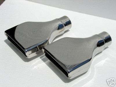 These are the exhaust tips we bought for the cut-outs.
They are from the new SSR Chevrolet truck released around 2006 I think. The main thing is they fit proportionatly to
the running boards and look very nice on Project COBRA'33.
|
|
| Weather-Pac 22-Pin Bulkhead Connector |
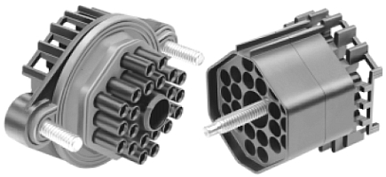
|
| We used 3 of these for Engine and Transmission Functions |
06-20-08
Wow...were getting very close to starting on the
body work......that is the kind the leads to pint, not the panel replacement like we have been doing !!
What seems to have taken forever has finally come to pass......the dash-AC-roll bar...have all been a long a drawn out affair.
Granted I have not been going to the shop as regularly as I have been in the past, but these areas still took loads of time.
There is no quick way around it, we had to finish one and then go to the next, as many times we had to work on an area, then
stop and get another area going, before we could finish or even further another area. This section had many inter-related
pieces that all had to be worked on together and separate, at the same time. I know it sounds goofy, but that is the case.
One area that we decided to leave till the last part of the project..was the steering. This is one area
I have had many doubts about. The area is very crowded and there is nearly no room to move things
around. I think it's almost impossible to truly locate the steering column, unless the body is on the frame and
the steering system from the back of the engine is bolted in. Those giant heads, take up so much room, there is just no way
around it. We will have to install the rack and pinion to the steering column, after the body is painted and bolted to the
chassis. This will make the task that much more difficult, but I see no way around it, we will just have to be very, very
careful.
Yesterday I was at the shop and Dad and I got several items going. First up was
the consol. Dad had already trimmed the excess metal from the frame, so we could start right away on it. The only problem
was the clearance between the passenger side and the roll bar, I removed the two tabs we welded on and moved the whole thing
over to the drivers side about 3/8" to gain clearance form the roll bar. This was fairly easy and Straight forwards,
and worked well. Next, I added several good Tach welds to the down bars and any other weld the looked week. We will have to
break the temporary welds holding the rear section to the front section, and remove the front cage assembly. I don't won’t
any of the structures to move before I get a chance to permanently weld them 100%, so this was a preliminary move. Next, Dad
and I started on the two top overhead bars that will house the overhead consol. These bars needed to be trimmed, so as Dad
did that, I went to work on locating and drilling the location for the three 22-Pin bulkhead wiring mounts. These are the
ones we built many months ago when we started the engine wiring harness. These harnesses we made, will plug into the bulkhead
fittings I am preparing, and allow the electrical circuits to pass through the fire wall, safely and without loss of signal.
Originally we made 2 22-pin harnesses and a few 3 and 4-pin connectors. I decided to change that and make all circuits pass
through the 22-pin connectors. This assures all circuits are equally protected from the weather, engine environment and are
also easy to access and un-plug. Latter I will have to make a few changes to the wiring harnesses we made, but that won't
be a big deal, I have to make some changes there any now. The big question was were to mount the bulkhead connectors?? I wanted
the location to be accessible and fairly protected, but I also wanted them to clear everything on the other side of the fire
wall and be somewhat hidden from view. Basically the whole passenger side of the firewall was taken up, the hose connections
and AC/Heater/Defroster unit took up that area. To make sure the connectors were well hidden but still accessible, I measured
the back of the engine from just above the bell-housing to the frame and then transferred that to the firewall. There is a
nice open area in the very back of the engine, the big heads on each side create a nice open spot, dead middle and from the
bell housing up to the top of the blower, I wanted to locate the first bulkhead connector as low as possible, without getting
into clearance issues with the engine or any of it's sub-systems. Because of the limited space under the dash and my only
window behind the engine, the three bulkheads connectors were alined from the bottom most area above the bell housing Straight
up in alignment one above the other. I needed roughly 4-1/2" from the center of one connector to the center of the other,
so the every top connector ended up only 3-4" down from the top of the firewall. Yes you will be able to see it, but
I did manage to hide the other two. To mount these bulkhead connectors, you must first drill a 2" hole then lay out the
centers and drill one 1/4" hole on each side, for the attachment bolts. The connectors themselves have a gasketing material
that will keep fumes and debris out of the inside area once they are installed and tightened down by the two mounting bolts.
And when it comes time to plug in the wiring harnesses for the engine compartment, you only have to push the appropriate connector
into it's mating plug and secure with a simple single mounting screw located in the center of the connector, very simple
and very factory like. Again...these three plugs will serve the engine and transmission functions and features.
Once the overhead consol bars were fitted and welded in place, we cleaned the interior area and installed the rear and front
seat frames. It was finally time to install the front seats and locate them properly!!.. Everything seemed to look and feel
right, just I needed to make a pedestal for the front seats to get them up roughly 7". This was a very pleasant surprise....I
hadn't figured on a pedestal, and especially not one so large. We decided that we would make one very similar to the rear
seat. I bent up some 1" square tube and made a U-bend on two different pieces, these two pieces will be welded together
with 5" long sections of 1" square tubing in between them to form a pedestal. This will lift and support the front
seat frame. I used plenty of support sections so it would be stout and very capable even in the worst condition, like an accident.
Nothing worse then the seat breaking away from the body.... The nice surprise from this pedestal is the added room I now have
for some items which might be installed under the seat and the added foot room the rear passengers will now have. Because
the front seat is now elevate, they can easily put there feet under the support, giving them much more room for an even better
rear seat experience.
We finished the day off by wrapping the pedestal in 18 Gauge sheet metal,
very much like we did the consol. Not sure if this will be covered when the interior is installed or not, but right now it
looks a lot like the old school bomber stuff, kind of neat. I did get some pictures of the front seats and
that but I will have to post them later, we are leaving soon for the Henry Ford Museum, in Allens Folk Michigan. I can't
wait to see the many old car & Trucks on display or the many locomotives they have. I went there ,many years ago and imagine
they have added a good deal of new exhibits by now? I also hope to take the Ford Rouge River Plant tour, I always find technology
interesting, and can't wait to see the new assembly plant in person.
We are so close to
starting the body work, I have been really busy trying to pick a color for the final body work. I don't wont black, I
normally like black but not on this car, it's to popular and back then it was the only color they offered. All other colors
are on the table, I jut need to find the one I like the best, I may even go with a multi-color scheme? I'll let you know
as soon as I figure it out, I am most likely going to go with a metallic or pearlescent candy color.
Once we drill the floor for the seat support, all I need to do is figure out how to hide a small area above the middle consol,
and the roll bar, it's an area about 1" wide and the width of the consol. I think we can just trim the mounting tabs
and tach on a piece that covers the area at about a 30-45 angel. This piece would rest it's top on the under dash roll
bar and it's bottom on the consol. The other item I need to address is how I'm going to get all my wiring from the
dash are to the rear of the car. There is many, many wires from the engine/transmission area that have to go to the rear area,
and then several that have to go from that same rear area to the dash, I would estimate somewhere around 100-120 wires in
all. I was thinking about making a small tunnel from the front seat support to the rear seat support, this would allow access
both ways and keep people from stepping on the wires. Then from the front of the front seat support to the dash, have another
tunnel, or maybe 3-4 conduits for the wires to travel through? I'll get more specific as the time comes closer to reality.
I'm still thinking now.
Once that is done, I can remove the front and rear roll bars and
start the body work. We will first re-sand blast the body, it will be a very quick one, there isn't anything on it this
time but some light surface rust and dirt. Then I will do a overall sand and cover it with a good quality epoxy etching primer.
Wasn't that done, then it's just attach each problem area and knock them off on at a time till we are left with a
car ready for final paint. If only it was that simple.
Oh yell, the 45̊ pipes came in and I'll get them on as time permits, this will finish off the exhaust system
and complete another area. I have been looking into getting a few items polished, as we grow nearer the completion,
I find myself looking more and more for those few items that will definitely set this car off and aprat from the rest as a
true show car. The 4.6L Ford isn't nearly as popular as say the Chevy 350, so there isn't the show parts available,
this is why I will have to take the more expensive route and have item polished. So far the items I am considering
are the exhaust system, intercooler-radiator, steering tank, Ac expansion Tank and a few other little things. The exhaust
system is Stainless Steel and would look killer polished, I have gotten a quote of $185.00 each side, which isn't that
bad, so It will most likely get polished. The other items are all aluminum and all together I would think
about $400.00. So figure shipping to and from were looking at $1000.00 -$1100.00 total.
Once we drill the floor for the seat support, all I need to do is figure out how to hide a small area above the middle consol,
and the roll bar, it's an area about 1" wide and the width of the consol. I think we can just trim the mounting tabs
and tach on a piece that covers the area at about a 30-45 angel. This piece would rest it's top on the under dash roll
bar and it's bottom on the consol. The other item I need to address is how I'm going to get all my wiring from the
dash are to the rear of the car. There is many, many wires from the engine/transmission area that have to go to the rear area,
and then several that have to go from that same rear area to the dash, I would estimate somewhere around 100-120 wires in
all. I was thinking about making a small tunnel from the front seat support to the rear seat support, this would allow access
both ways and keep people from stepping on the wires. Then from the front of the front seat support to the dash, have another
tunnel, or maybe 3-4 conduits for the wires to travel through? I'll get more specific as the time comes closer to reality.
I'm still thinking now.
Once that is done, I can remove the front and rear roll bars and
start the body work. We will first re-sand blast the body, it will be a very quick one, there isn't anything on it this
time but some light surface rust and dirt. Then I will do a overall sand and cover it with a good quality epoxy etching primer.
Wasn't that done, then it's just attach each problem area and knock them off on at a time till we are left with a
car ready for final paint. If only it was that simple.
Oh yell, the 45̊ pipes came in and I'll get them on as time permits, this will finish off the exhaust system
and complete another area. I have been looking into getting a few items polished, as we grow nearer the completion,
I find myself looking more and more for those few items that will definitely set this car off and aprat from the rest as a
true show car. The 4.6L Ford isn't nearly as popular as say the Chevy 350, so there isn't the show parts available,
this is why I will have to take the more expensive route and have item polished. So far the items I am considering
are the exhaust system, intercooler-radiator, steering tank, Ac expansion Tank and a few other little things. The exhaust
system is Stainless Steel and would look killer polished, I have gotten a quote of $185.00 each side, which isn't that
bad, so It will most likely get polished. The other items are all aluminum and all together I would think
about $400.00. So figure shipping to and from were looking at $1000.00 -$1100.00 total. |
|
| Front Seat Pedestal |
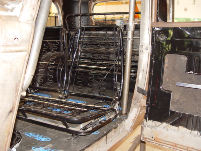
|
| Secondary Exhaust Outlet |
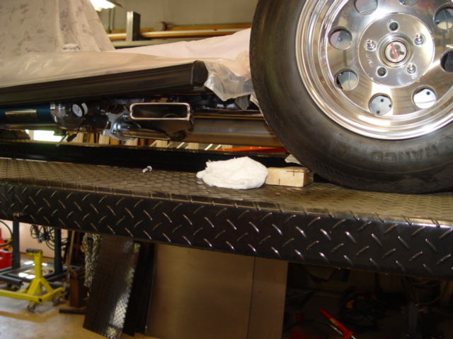
|
| Looking from The Winters Quick Change Front |
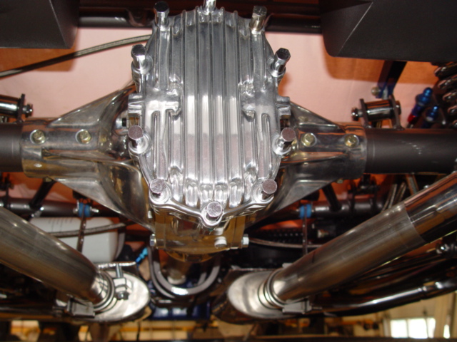
|
| Winters Quick Change Forward |
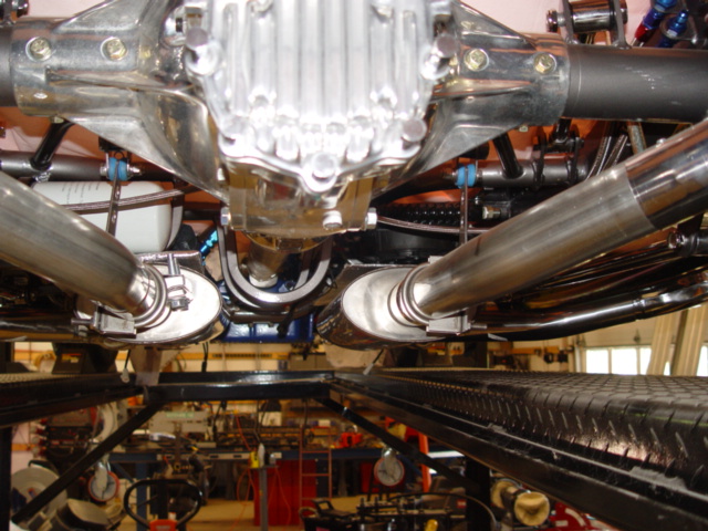
|
| Borla Exhaust System |
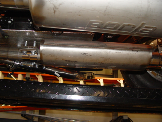
|
| Front Seat Pedestal |
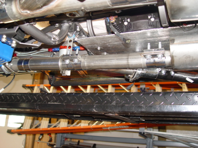
|
| Front Seat Pedestal |
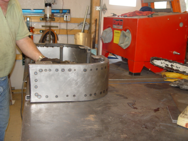
|
| Front Seat Pedestal |
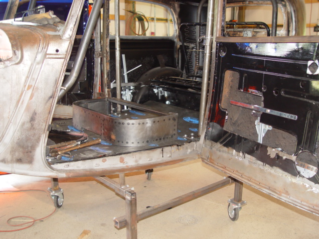
|
| Front Seat Pedestal |
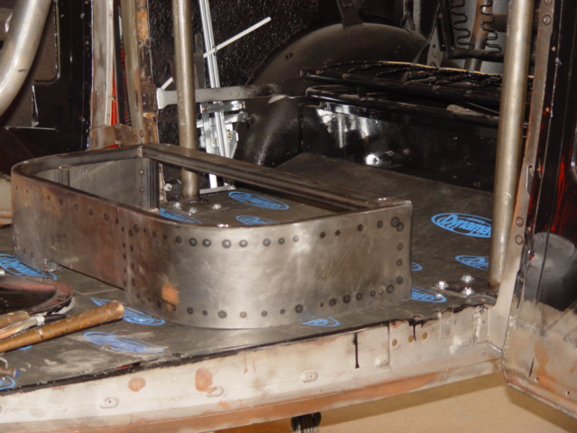
|
| Here as well as above you can see the opening in the middle for the wiring. |
06-24-08
I have to tell you about the recent trip we took to the
Henry Ford Museum, It was simply wonderful and very inspiring and interesting. You could watch a show about the thing 10 times
at home and still never get the vastness of the place, or just how great the man was. Henry Ford was a brilliant engineer,
but more importantly he made a vision and drive seen by very few. He was also a very giving individual, the charities and
places he supported and established are almost unprecedented. I would challenge anyone to find a more giving person.
The first day we visited the Greenwich Village. This a huge 90+acres establishment set on preserving
the building and way of life, of many of the countries best know inventors. Thomas Jefferson, Thomas Edison, Henry Ford and
others have there birth places, work shops and more painstaking disassembled and transferred here, where they rebuilt them
exactly like they were. There is one of the old working farms, Fords farm there, glass blower shop, wheel wright shop, machine
shops, printing press shop, textile shop, there is also the oldest working Post office in America there. The neat twist about
Greenwich Village is the people that work there, they are all in period dress, and perform actual jobs, and products, some
are for sale in the gift shops. Where else can you ride in a original and working Model T?, a live and oftlinefunctional steam
engine, or drive around the place in a horse drawn buggy. Even the food shops sell period food, if you have the time and imagination,
you can go back in time and re-live the past. I found the whole village readable and very pleasing, I hope you get a chance
to visit there as well.
The Henry Ford Museum was another great trip. They have everything to remember the
United States greatest events and inventions. Of-coarse they have many automobiles and several wonderful exhibits on display,
but they also have machines, airplanes, social issues and documents that changed our country. If you like steam engines, they
have many on display, all of which I found interesting and amazed by. I still have no ideal how they made those huge crankshafts,
pistons, flywheels and generators, it would be a feat for today’s technology. There were other mini showings as well,
like the ones on time and clocks, metals, important documents and civil rights. The most impressive display was a locomotive
of the Allegheny class, wow that is a train engine. I found the entire place interesting and informative, the only problem
was they didn't have one 1933-34 car on display, I was looking forward to seeing one.
We also visited the Rouge River
Assembly Plant now known as the Dearborn Assembly Plant. There they make the Ford F-150 trucks, the two
movies you see are the most interesting,
they really give you a since of what it takes to produce a automobile. The assembly line was down, and just the day before
Ford had all there top dealers from around the USA in for a special meeting. Because of the sudden drop in demand for the
trucks and SUV's, ford along with there dealers decided to suspend building anymore Ford F-150's for 4 months.....I
sure hope they survive this bad economy, I'm really worried about them. They also decided to curtail other assembly lines
that make the F-250,350 and SUV. Good news for some was the new Edge, Fussion, Mustang and Focus are selling well and they
had to add production of those units.
I go to go down to the shop today and we finished the front
seat pedestal. We had to cut a section from the front, dead middle to allow the wiring harnesses to pass through. This involved
cutting the 1" x 1" square tubing out and them trimming the sheet metal off. Once that was done, we welded on the
four mounting tabs, Dad had already made. When we went to position the pedestal in the car, it fit pretty good and we decided
on a measurement of 29" from lower door trim to back edge of pedestal. We drilled the mounting holes and then mounted
the front seat and checked the fit and comfort. For me it will be a skosh tight, but nothing un-bearable. Next we removed
everything from the front and went to work on the rear seat pedestal. We needed to notch the pedestal like we did the front
one, again for wires to pass through. While Dad worked on this, I went over to the frame and got to installing the rest of
the exhaust system. We were waiting on the 2-45 bends to come in, before we could finish the secondary exhaust system. Now
that I had them it was really easy to finish, I just had to trim 3" off one side of both 45 bends and install. There
was some light tweaking, but only simple stuff like rotating the Y-pipe or exhaust cut-out motor. The end result looks nice,
I like how they poke out from under the running boards. These two new bends came polished, I had been contemplating polishing
the rest of the exhaust system, and now I have a better ideal how it would look....Very Nice! I'll leave the polishing
for latter, and I’ll see how the money holds out. I did make a list of what should be polished and there sizes for a
more accurate estimate.
Another small project I got finished was the power vent motor. I had been worrying about it there
would be enough room to mount it, but it worked out just fine. I used a small portion of the bracket we made for the AC Unit
to mount the small motor to, the rest just bolted to the vent frame, and that was it. I did temporarily bring a 12-Volt source
out to the body to operated the motor and make sure there were no issues. it worked fine and who would have thought that would
be the very first electrical component installed on the car ??
The overhead consol. we also figured
out, it is not going to be as elaborate or big as I first thought, I just need it to mount the overhead video screen to. I determined
we would simply cut a piece of 1/8" thick metal approximately 9-1/4" x 10-1/2" long and tach it in between
the two middle overhead bars. I will not need to mount anything else up there, I now have plenty of room with the front seat
pedestal. Dad will get the plate ready and next visit I will tach it in. In fact once that is done, the next
time I go down to the shop we will be un-bolting everything from the interior of the body and getting it ready for body work!!
We are to that point, which means we are only a small amount away from color!!!. Of-which I have not decided on, I have been
doing a lot of thinking on it...I'll make my decision soon.
I have to tell you about
the recent trip we took to the Henry Ford Museum, It was simply wonderful and very inspiring and interesting. You could watch
a show about the thing 10 times at home and still never get the vastness of the place, or just how great the man was. Henry
Ford was a brilliant engineer, but more importantly he made a vision and drive seen by very few. He was also a very giving
individual, the charities and places he supported and established are almost unprecedented. I would challenge anyone to find
a more giving person.
The first day we visited the Greenwich Village. This a huge 90+acres establishment set on
preserving the building and way of life, of many of the countries best know inventors. Thomas Jefferson, Thomas Edison, Henry
Ford and others have there birth places, work shops and more painstaking disassembled and transferred here, where they rebuilt
them exactly like they were. There is one of the old working farms, Fords farm there, glass blower shop, wheel wright shop,
machine shops, printing press shop, textile shop, there is also the oldest working Post office in America there. The neat
twist about Greenwich Village is the people that work there, they are all in period dress, and perform actual jobs, and products,
some are for sale in the gift shops. Where else can you ride in a original and working Model T?, a live and functional steam
engine, or drive around the place in a horse drawn buggy. Even the food shops sell period food, if you have the time and imagination,
you can go back in time and re-live the past. I found the whole village readable and very pleasing, I hope you get a chance
to visit there as well.
The Henry Ford Museum was another great trip. They have everything to remember the United States
greatest events and inventions. Of-coarse they have many automobiles and several wonderful exhibits on display, but they also
have machines, airplanes, social issues and documents that changed our country. If you like steam engines, they have many
on display, all of which I found interesting and amazed by. I still have no ideal how they made those huge crankshafts, pistons,
flywheels and generators, it would be a feat for today’s technology. There were other mini showings as well, like the
ones on time and clocks, metals, important documents and civil rights. The most impressive display was a locomotive of the
Allegheny class, wow that is a train engine. I found the entire place interesting and informative, the only problem was they
didn't have one 1933-34 car on display, I was looking forward to seeing one.
We also visited the Rouge River Assembly
Plant now known as the Dearborn Assembly Plant. There they make the Ford F-150 trucks, the two movies you see are the most
interesting, they really give you a since of what it takes to produce a automobile. The assembly line was down, and just the
day before Ford had all there top dealers from around the USA in for a special meeting. Because of the sudden drop in demand
for the trucks and SUV's, ford along with there dealers decided to suspend building anymore Ford F-150's for 4 months.....I
sure hope they survive this bad economy, I'm really worried about them. They also decided to curtail other assembly lines
that make the F-250,350 and SUV. Good news for some was the new Edge, Fussion, Mustang and Focus are selling well and they
had to add production of those units.
I got to go down to the shop today and we finished the front seat pedestal.
We had to cut a section from the front, dead middle to allow the wiring harnesses to pass through. This involved cutting the
1" x 1" square tubing out and them trimming the sheet metal off. Once that was done, we welded on the four mounting
tabs, Dad had already made. When we went to position the pedestal in the car, it fit pretty good and we decided on a measurement
of 29" from lower door trim to back edge of pedestal. We drilled the mounting holes and then mounted the front seat and
checked the fit and comfort. For me it will be a skosh tight, but nothing un-bearable. Next we removed everything from the
front and went to work on the rear seat pedestal. We needed to notch the pedestal like we did the front one, again for wires
to pass through. While Dad worked on this, I went over to the frame and got to installing the rest of the exhaust system.
We were waiting on the 2-45̊ bends to come in, before we could finish the secondary exhaust
system. Now that I had them it was really easy to finish, I just had to trim 3" off one side of both 45 bends and install.
There was some light tweaking, but only simple stuff like rotating the Y-pipe or exhaust cut-out motor. The end result looks
nice, I like how they poke out from under the running boards. These two new bends came polished, I had been contemplating
polishing the rest of the exhaust system, and now I have a better ideal how it would look....Very Nice! I'll leave the
polishing for latter, and I’ll see how the money holds out. I did make a list of what should be polished and there sizes
for a more accurate estimate.
Another small project I got finished was the power vent motor. I had been worrying about
if there would be enough room to mount it, but it worked out just fine. I used a small portion of the bracket we made for
the AC Unit to mount the small motor to, the rest just bolted to the vent frame, and that was it. I did temporarily bring
a 12-Volt source out to the body to operated the motor and make sure there were no issues. it worked fine and who would have
thought that would be the very first electrical component installed on the car ??
The overhead
consol... we also figured out, it is not going to be as elaborate or big as I first thought, I just need it to
mount the overhead video screen to. I determined we would simply cut a piece of 1/8" thick metal approximately 9-1/4"
x 10-1/2" long and tach it in between the two middle overhead bars. I will not need to mount anything else up there,
I now have plenty of room with the front seat pedestal. Dad will get the plate ready and next visit I will tach it in. In
fact once that is done, the next time I go down to the shop we will be un-bolting everything from the interior of the body
and getting it ready for body work!! We are to that point, which means we are only a small amount away from color!!!. Of-which
I have not decided on, I have been doing a lot of thinking on it...I'll make my decision soon.
07-01-08
July....Time is not so slowly ticking by, we will really have to take it up a
notch if we are to paint this car by Fall.
This will be the end for Frame Build-up VIII, the next instalment will be
on the Body and the Paint prep work. But before we close this chapter, lets up-date you first.
The body is coming along,
we removed the roll cage, AC Unit, Power vent motor, seat risers and anything else that was bolted in. We will fully weld-out
the roll cage as time permits, but we figured out we will have to leave it in 3-pieces. Other wise it will not go back in,
so there will be the back portion, center roll bar and front section. When the time comes, we will re-assemble the roll cage
inside the car and then weld it together, using the open roof for the access. Once it's welded together, it is in there
for good! I'll paint all surfaces except for the immediate area around the late welds, then I can simply pain that small
area.
We started the body work today, I was filling some holes in the rear section while dad did the same on his side.
We filled the frame mounting holes that you would see in the rear fender well, we don't need them and it will look better
without them. I also got a few depressions filled, and we tach welded some more around the rocker panel fill plate. Up front
I started grinding on the firewall, and knocking down any high areas, it looks pretty good already, and only needs some light
sanding and contour work in a few tight places. There will be a few long seams that I will fill later, these are the seams
created when we sectioned the firewall, so the engine would clear. Right now I'm going to concentrate on the general body
and sanding it for Sealer/primer. I will go over the out side once again with the sand blaster, just this time I'll do
the job myself. Our first step toward a finished body is prepping the outside sheet metal for the Bare Metal Primer/Sealer,
then we can turn our attention to the body work portion of the job.
Up top, on the roof, I went around the section that
holds the roofing material and removed all the tacks. The wood insert that you tack into is pretty rough, so I'm thinking
about what I can use to build this area up. I need it to be strong enough to hold when we tack the new roof material in place.
I noticed one small hole in the center back part of the roof, so we will have to patch that area. I'll just tach a small
section of sheet metal from the bottom, and fill the hole. I have to use the back-up metal, because the area is very thin
and would not hold on it's own.
Well, this about does it for this section, so ...see you in the body work section.
The overhead consol... we also figured out, it is not going to be as elaborate or big as I first thought,
I just need it to mount the overhead video screen to. I determined we would simply cut a piece of 1/8" thick metal
approximately 9-1/4" x 10-1/2" long and tach it in between the two middle overhead bars. I will not need to mount
anything else up there, I now have plenty of room with the front seat pedestal. Dad will get the plate ready and next visit
I will tach it in. In fact once that is done, the next time I go down to the shop we will be un-bolting everything from the
interior of the body and getting it ready for body work!! We are to that point, which means we are only a small amount away
from color!!!. Of-which I have not decided on, I have been doing a lot of thinking on it...I'll make my decision soon.
07-01-08
July....Time is not so slowly ticking by, we will really have to
take it up a notch if we are to paint this car by Fall.
This will be the end for Frame Build-up VIII, the next instalment
will be on the Body and the Paint prep work. But before we close this chapter, lets up-date you first.
The body is coming
along, we removed the roll cage, AC Unit, Power vent motor, seat risers and anything else that was bolted in. We will fully
weld-out the roll cage as time permits, but we figured out we will have to leave it in 3-pieces. Other wise it will not go
back in, so there will be the back portion, center roll bar and front section. When the time comes, we will re-assemble the
roll cage inside the car and then weld it together, using the open roof for the access. Once it's welded together, it
is in there for good! I'll paint all surfaces except for the immediate area around the late welds, then I can simply pain
that small area.
We started the body work today, I was filling some holes in the rear section while dad did the same
on his side. We filled the frame mounting holes that you would see in the rear fender well, we don't need them and it
will look better without them. I also got a few depressions filled, and we tach welded some more around the rocker panel fill
plate. Up front I started grinding on the firewall, and knocking down any high areas, it looks pretty good already, and only
needs some light sanding and contour work in a few tight places. There will be a few long seams that I will fill later, these
are the seams created when we sectioned the firewall, so the engine would clear. Right now I'm going to concentrate on
the general body and sanding it for Sealer/primer. I will go over the out side once again with the sand blaster, just this
time I'll do the job myself. Our first step toward a finished body is prepping the outside sheet metal for the Bare Metal
Primer/Sealer, then we can turn our attention to the body work portion of the job.
Up top, on the roof, I went around
the section that holds the roofing material and removed all the tacks. The wood insert that you tack into is pretty rough,
so I'm thinking about what I can use to build this area up. I need it to be strong enough to hold when we tack the new
roof material in place. I noticed one small hole in the center back part of the roof, so we will have to patch that area.
I'll just tach a small section of sheet metal from the bottom, and fill the hole. I have to use the back-up metal, because
the area is very thin and would not hold on it's own.
Well, this about does it for this section, so ...see you in
the body work section.
Enter supporting content here
Pro Weld
5937 Ethan Drive
Burlington, KY 41005
859-586-4069
Proweld@myway.com
|
|
|
|